Dodge Dakota (ND). Manual — part 216
*NO RESPONSE FROM FCM (FRONT CONTROL MODULE) (CONTINUED)
For a complete wiring diagram Refer to Section 8W.
Possible Causes
(A918) FUSED B (+) CIRCUIT OPEN AT DLC
(Z11) GROUND CIRCUIT OPEN AT DLC
GROUND CIRCUITS OPEN AT FCM
FUSED B+ CIRCUITS OPEN AT FCM
FRONT CONTROL MODULE
Diagnostic Test
1.
TEST FOR INTERMITTENT CONDITION
Turn the ignition on.
NOTE: Ensure the IOD fuse is installed and battery voltage is between 10.0 and 16.0 volts.
NOTE: Ensure the scan tool is updated to the latest software.
NOTE: If the scan tool displays any error messages involving the CAN C Diagnostic circuits, diagnose and
repair the error message before proceeding. Refer to the Table of Contents.
NOTE: A loss of communication with the FCM can cause the ECU View button on the scan tool to be inop-
erative (not highlighted).
With the scan tool, attempt to select ECU view.
Can the scan tool communicate with the FCM?
Yes
>> The no response condition is not present at this time. Using the wiring diagram/schematic as a guide,
inspect the wiring for chafed, pierced, pinched, and partially broken wires and the wiring harness con-
nectors for broken, bent , pushed out, and corroded terminals.
No
>> Go To 2
2.
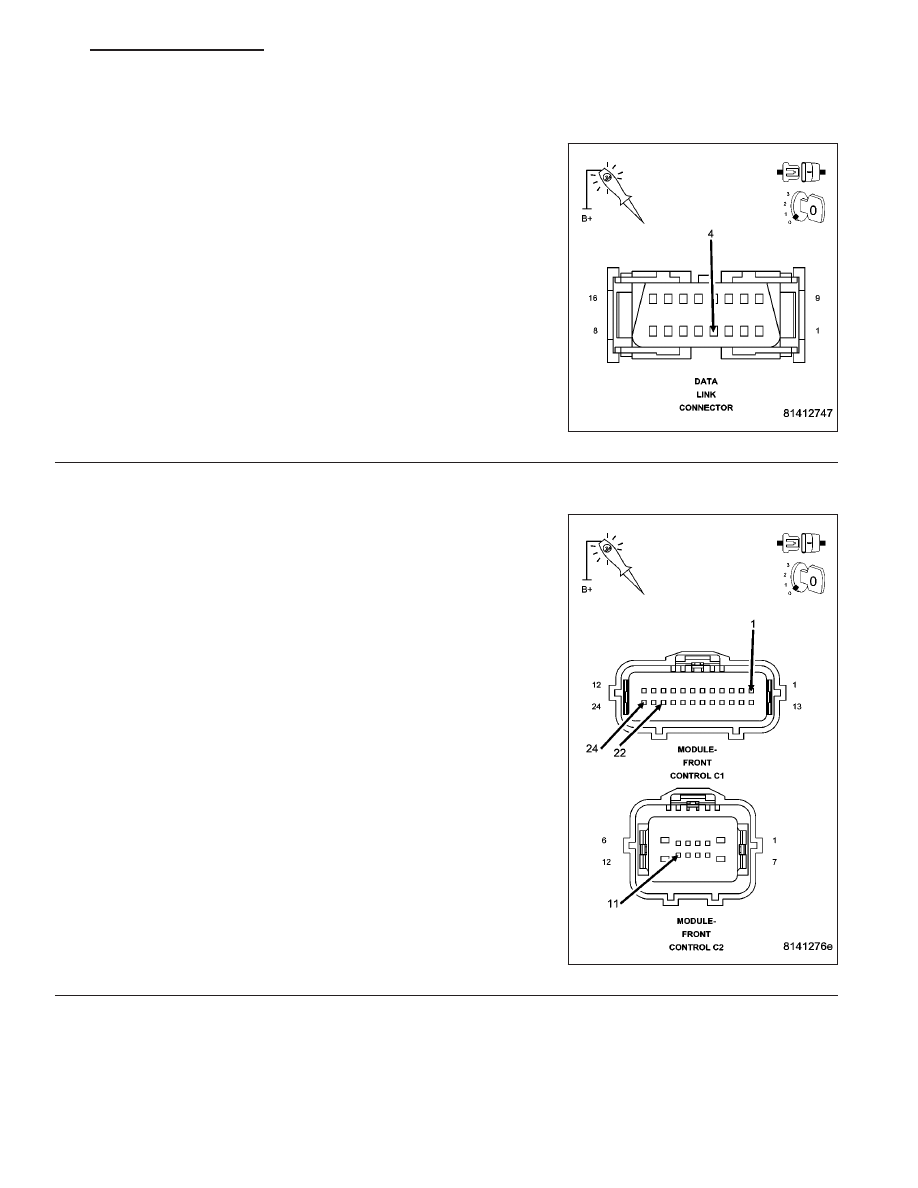
(A918) FUSED B(+) CIRCUIT OPEN AT DLC
Disconnect the scan tool from the DLC.
Using a 12-volt test light connected to ground, check the (A918) Fused
B(+) circuit.
Does the test light illuminate brightly?
Yes
>> Go To 3
No
>> Repair the (A918) Fused B(+) circuit for an open or short.
Perform BODY VERIFICATION TEST - VER 1. (Refer to
BODY VERIFICATION TEST - VER 1).
8E - 120
ELECTRONIC CONTROL MODULES - ELECTRICAL DIAGNOSTICS
ND
*NO RESPONSE FROM FCM (FRONT CONTROL MODULE) (CONTINUED)
3.
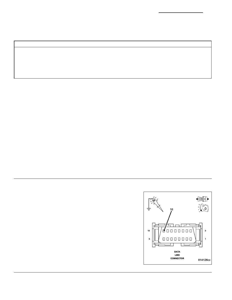
(Z11) GROUND CIRCUIT OPEN AT DLC
Using a 12-volt test light connected to 12-volts, check the (Z11)
ground circuit.
Does the test light illuminate brightly?
Yes
>> Go To 4
No
>> Repair the (Z11) ground circuit for an open.
Perform BODY VERIFICATION TEST - VER 1. (Refer to
BODY VERIFICATION TEST - VER 1).
4.
GROUND CIRCUITS OPEN AT FCM C1 AND C2 CONNECTORS
Disconnect the FCM C1 and C2 harness connectors.
Using a 12-volt test light connected to 12-volts, check each ground cir-
cuit.
Does the test light illuminate brightly for each circuit?
Yes
>> Go To 5
No
>> Repair the ground circuit for an open. Inspect the connec-
tor for damage.
Perform BODY VERIFICATION TEST - VER 1. (Refer to
BODY VERIFICATION TEST - VER 1).
ND
ELECTRONIC CONTROL MODULES - ELECTRICAL DIAGNOSTICS
8E - 121
*NO RESPONSE FROM FCM (FRONT CONTROL MODULE) (CONTINUED)
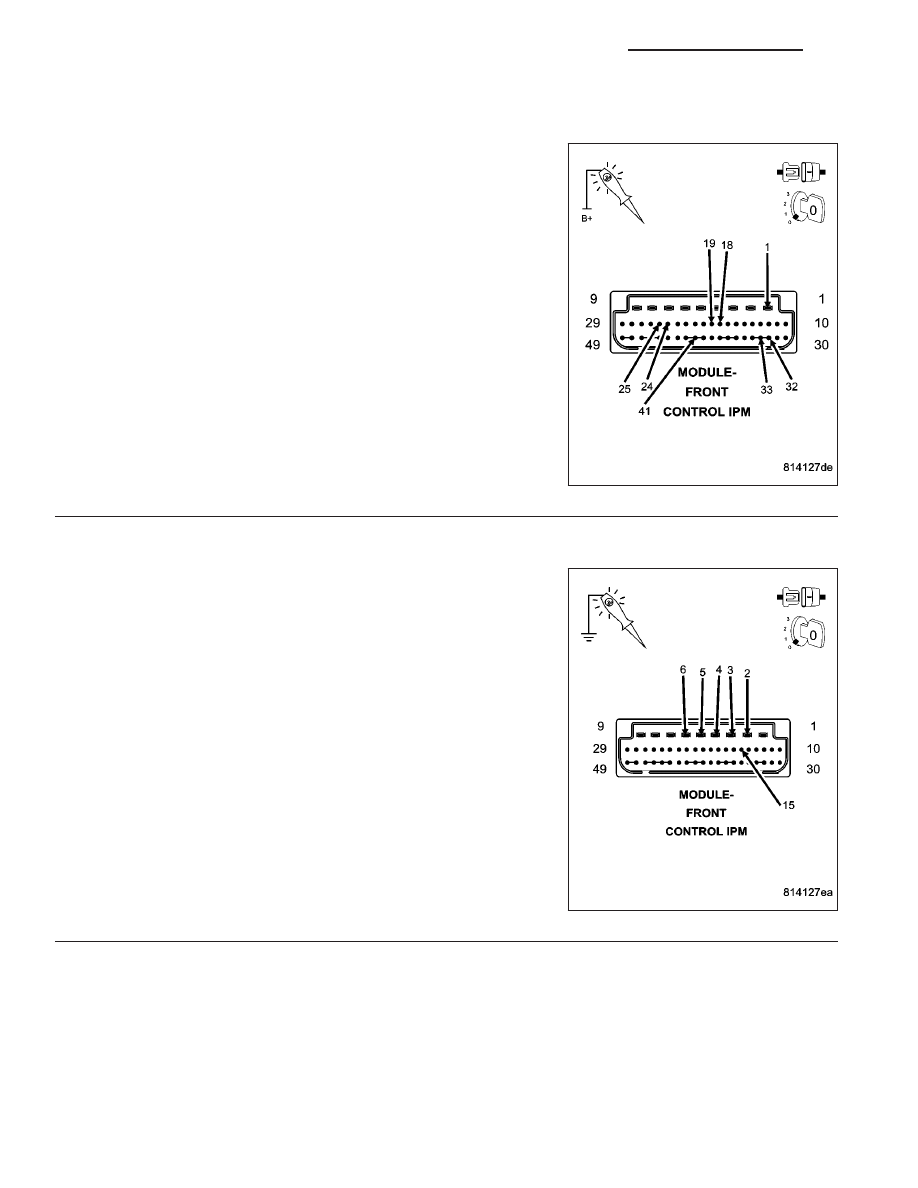
5.
GROUND CIRCUITS OPEN AT FCM IPM CONNECTOR
Remove the FCM from the IPM.
Using a 12-volt test light connected to 12-volts, check each ground cir-
cuit.
Does the test light illuminate brightly for each circuit?
Yes
>> Go To 6
No
>> Repair the ground circuit for an open. Inspect the connec-
tor for damage.
Perform BODY VERIFICATION TEST - VER 1. (Refer to
BODY VERIFICATION TEST - VER 1).
6.
FUSED B(+) CIRCUITS OPEN AT FCM IPM CONNECTOR
Using a 12-volt test light connected to ground, check each Fused B(+)
circuit.
Does the test light illuminate brightly for each circuit?
Yes
>> Replace and program the Front Control Module in accor-
dance with the service information.
Perform BODY VERIFICATION TEST - VER 1. (Refer to
BODY VERIFICATION TEST - VER 1).
No
>> Repair the Fused B(+) circuit for an open. Inspect the con-
nector for damage.
Perform BODY VERIFICATION TEST - VER 1. (Refer to
BODY VERIFICATION TEST - VER 1).
8E - 122
ELECTRONIC CONTROL MODULES - ELECTRICAL DIAGNOSTICS
ND
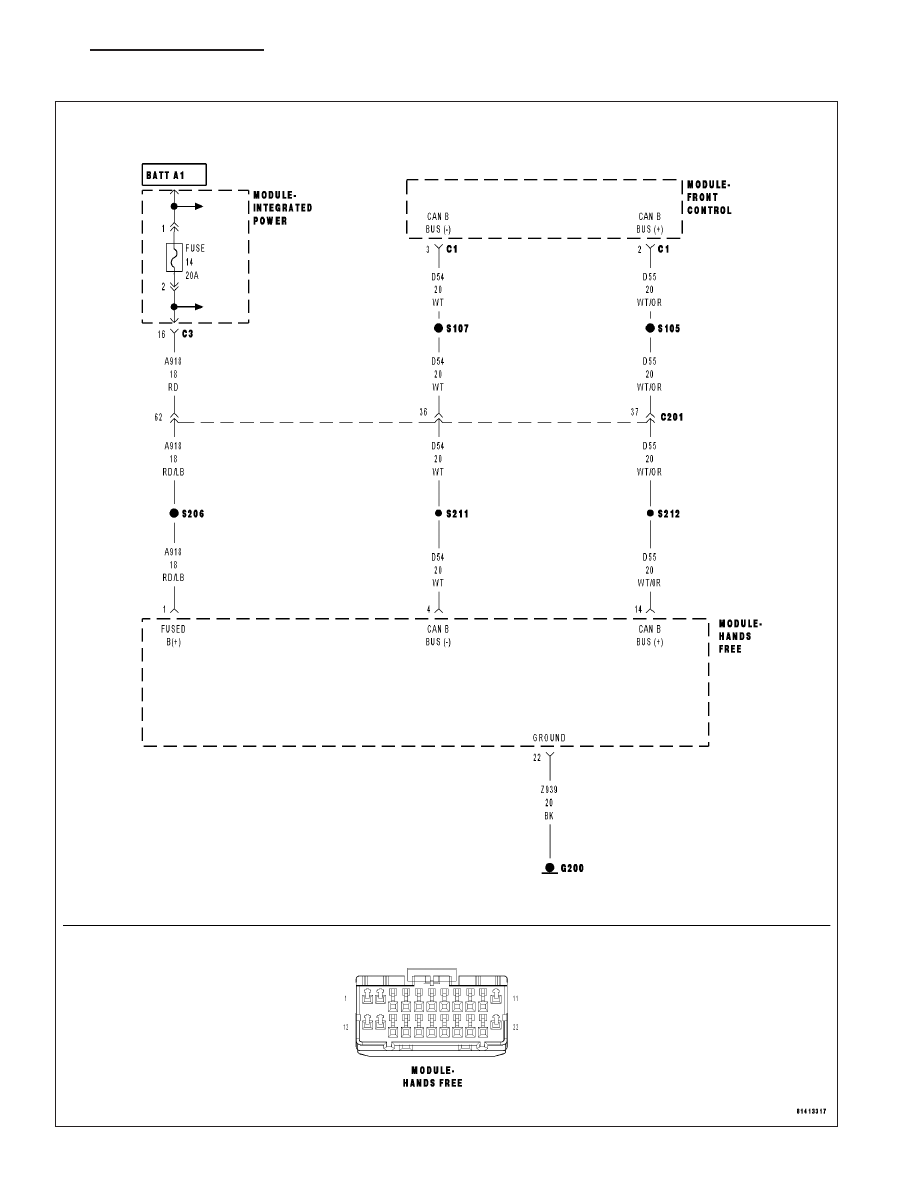
*NO RESPONSE FROM HFM (HANDS FREE MODULE)
ND
ELECTRONIC CONTROL MODULES - ELECTRICAL DIAGNOSTICS
8E - 123
Нет комментариевНе стесняйтесь поделиться с нами вашим ценным мнением.
Текст