Dodge Dakota (ND). Manual — part 831
1. Start the engine.
2. Spray a small stream of water (spray bottle) at the suspected leak area.
3. If engine RPM’S change, the area of the suspected leak has been found.
4. Repair as required.
REMOVAL
1. Disconnect negative cable from battery.
2. Remove resonator assembly and air inlet hose.
3. Disconnect throttle and speed control cables.
4. Disconnect electrical connectors for the following components: Refer to FUEL SYSTEM for component locations.
•
Manifold Absolute Pressure (MAP) Sensor
•
Intake Air Temperature (IAT) Sensor
•
Throttle Position (TPS) Sensor
•
Coolant Temperature (CTS) Sensor
•
Idle Air Control (IAC) Motor
5. Disconnect vapor purge hose, brake booster hose, speed control servo hose, positive crankcase ventilation
(PCV) hose.
6. Disconnect generator electrical connections.
7. Disconnect air conditioning compressor electrical connections.
8. Disconnect left and right radio suppressor straps.
9. Disconnect and remove ignition coil towers.
10. Remove top oil dipstick tube retaining bolt and ground strap.
11. Bleed fuel system (Refer to 14 - FUEL SYSTEM/FUEL DELIVERY - STANDARD PROCEDURE).
12. Remove fuel rail.
13. Remove throttle body assembly and mounting bracket.
14. Drain cooling system below coolant temperature level (Refer to 7 - COOLING - STANDARD PROCEDURE).
15. Remove the heater hoses from the engine front cover and the heater core.
16. Unclip and remove heater hoses and tubes from intake manifold.
17. Remove coolant temperature sensor (Refer to 7 - COOLING/ENGINE/ENGINE COOLANT TEMP SENSOR -
REMOVAL) .
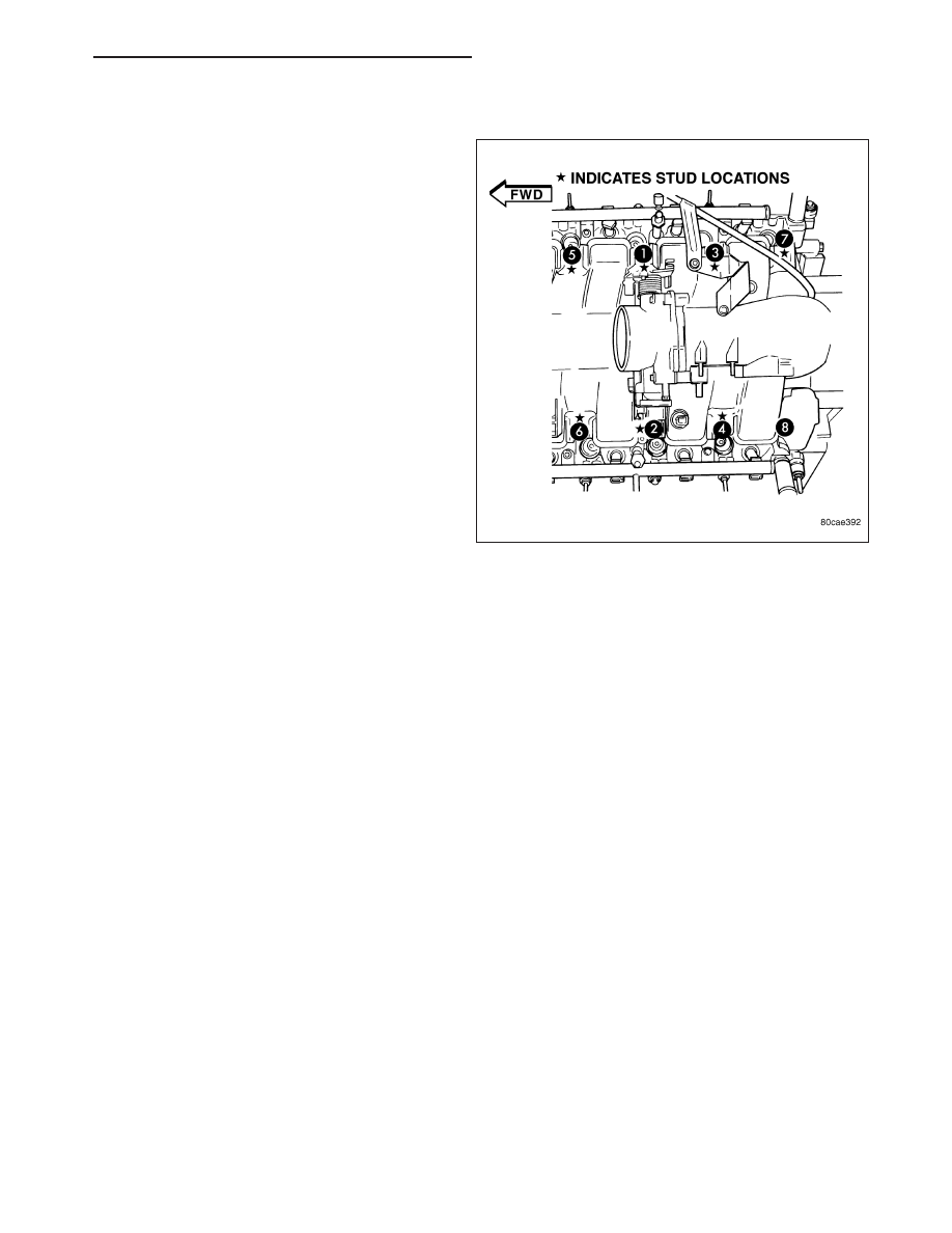
18. Remove intake manifold retaining fasteners in reverse order of tightening sequence.
19. Remove intake manifold.
9 - 862
ENGINE - 3.7L SERVICE INFORMATION
ND
INSTALLATION
1. Install intake manifold gaskets.
2. Install intake manifold.
3. Install intake manifold retaining bolts and tighten in
sequence shown in to 12 N·m (105 in. lbs.).
4. Install left and right radio suppressor straps.
5. Install throttle body assembly.
6. Connect throttle cable and speed control cable to
throttle body.
7. Install fuel rail.
8. Install ignition coil towers.
9. Position and install heater hoses and tubes onto
intake manifold.
10. Install the heater hoses to the heater core and
engine front cover.
11. Connect electrical connectors for the following
components:
•
Manifold Absolute Pressure (MAP) Sensor
•
Intake Air Temperature (IAT) Sensor
•
Throttle Position (TPS) Sensor
•
Coolant Temperature (CTS) Sensor
•
Idle Air Control (IAC) Motor
•
Ignition coil towers
•
Fuel injectors
12. Install top oil dipstick tube retaining bolt and ground strap.
13. Connect generator electrical connections.
14. Connect Vapor purge hose, Brake booster hose, Speed control servo hose, Positive crankcase ventilation
(PCV) hose.
15. Fill cooling system (Refer to 7 - COOLING - STANDARD PROCEDURE).
16. Install resonator assembly and air inlet hose.
17. Connect negative cable to battery.
ND
ENGINE - 3.7L SERVICE INFORMATION
9 - 863
MANIFOLD-EXHAUST
DESCRIPTION
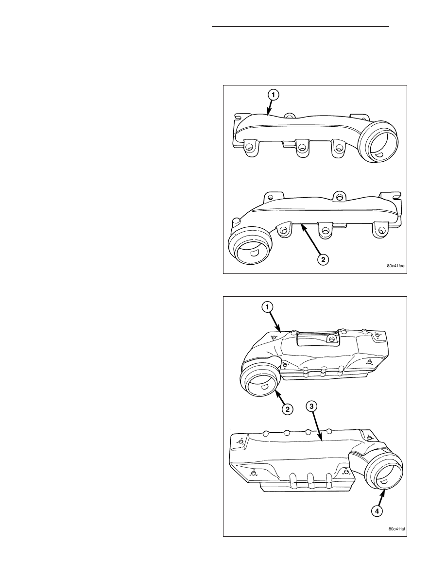
The exhaust manifolds( 1 and 2) are log style with a
patented flow enhancing design to maximize perfor-
mance. The exhaust manifolds are made of high sili-
con molybdenum cast iron. A perforated core graphite
exhaust manifold gasket is used to improve sealing to
the cylinder head.
The exhaust manifolds are covered by a three layer
laminated heat shield ( 1 and 3) for thermal protection
and noise reduction. The heat shields(1 and 3) are
fastened with a torque prevailing nut that is backed off
slightly to allow for the thermal expansion of the
exhaust manifold.
9 - 864
ENGINE - 3.7L SERVICE INFORMATION
ND
REMOVAL
RIGHT EXHAUST MANIFOLD
1. Disconnect the negative cable from the battery.
2. Raise and support the vehicle.
3. Remove the bolts and nuts attaching the exhaust
pipe to the engine exhaust manifold.
4. Lower the vehicle.
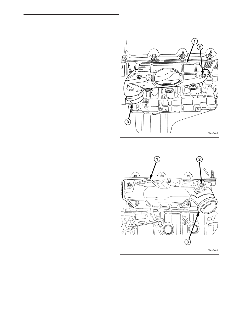
5. Remove the exhaust heat shield (1).
6. Remove bolts, nuts (2) and washers attaching
manifold to cylinder head.
7. Remove manifold and gasket from the cylinder
head.
LEFT EXHAUST MANIFOLD
1. Disconnect the negative cable from the battery.
2. Raise and support the vehicle.
3. Remove the bolts and nuts attaching the exhaust
pipe to the engine exhaust manifold.
4. Lower the vehicle.
5. Remove the exhaust heat shields (1).
6. Remove bolts, nuts (2) and washers attaching
manifold to cylinder head.
7. Remove manifold and gasket from the cylinder
head.
INSTALLATION
RIGHT EXHAUST MANIFOLD
CAUTION: If the studs came out with the nuts when removing the engine exhaust manifold, install new
studs. Apply sealer on the coarse thread ends. Water leaks may develop at the studs if this precaution is
not taken.
ND
ENGINE - 3.7L SERVICE INFORMATION
9 - 865
Нет комментариевНе стесняйтесь поделиться с нами вашим ценным мнением.
Текст