Dodge Dakota (ND). Manual — part 708
P0335-CRANKSHAFT POSITION SENSOR CIRCUIT (CONTINUED)
12.
(F855) 5-VOLT SUPPLY CIRCUIT SHORTED TO GROUND
Measure the resistance between ground and the (F855) 5-volt Supply
circuit in the CKP Sensor harness connector.
Is the resistance below 100 ohms?
Yes
>> Repair the short to ground in the (F855) 5-volt Supply cir-
cuit.
Perform the POWERTRAIN VERIFICATION TEST. (Refer
to 9 - ENGINE - STANDARD PROCEDURE)
No
>> Go To 13
13.
PCM
NOTE: Before continuing, check the PCM harness connector terminals for corrosion, damage, or terminal
push out. Repair as necessary.
Using the schematics as a guide, inspect the wire harness and connectors. Pay particular attention to all Power and
Ground circuits.
Were there any problems found?
Yes
>> Repair as necessary.
Perform the POWERTRAIN VERIFICATION TEST. (Refer to 9 - ENGINE - STANDARD PROCEDURE)
No
>> Replace and program the Powertrain Control Module per Service Information.
Perform the POWERTRAIN VERIFICATION TEST. (Refer to 9 - ENGINE - STANDARD PROCEDURE)
9 - 370
ENGINE ELECTRICAL DIAGNOSTICS
ND
P0335-CRANKSHAFT POSITION SENSOR CIRCUIT (CONTINUED)
14.
ERRATIC CKP SENSOR SIGNAL
Turn the ignition off.
With a lab scope probe and the Miller special tool #6801, backprobe the (K24) CKP Signal circuit in the CKP har-
nessconnector.
WARNING: When the engine is operating, do not stand in direct line with the fan. Do not put your hands
near the pulleys, belts, or fan. Do not wear loose clothing. Failure to follow these instructions can result in
personal injury or death.
Ignition on, engine not running.
Wiggle the related wire harness and lightly tap on the Crank Position Sensor.
Observe the lab scope screen.
Look for any pulses generated by the CKP Sensor.
Allow the engine to idle.
Observe the lab scope screen.
Did the CKP Sensor generate any erratic pulses?
Yes
>> Inspect the related wire harness and replace the Crankshaft Position Sensor if no wiring problems were
found.
Perform the POWERTRAIN VERIFICATION TEST. (Refer to 9 - ENGINE - STANDARD PROCEDURE)
No
>> Go To 15
15.
ERRATIC CMP SIGNAL
Turn the ignition off.
With a lab scope probe and the Miller special tool #6801, backprobe the (K44) CMP Signal circuit in the CMP
harness connector.
WARNING: When the engine is operating, do not stand in direct line with the fan. Do not put your hands
near the pulleys, belts, or fan. Do not wear loose clothing. Failure to follow these instructions can result in
personal injury or death.
Ignition on, engine not running.
Wiggle the related wire harness and lightly tap on the Cam Position Sensor.
Observe the lab scope screen.
Look for any pulses generated by the CMP Sensor.
Allow the engine to idle.
Observe the lab scope screen.
Did the CMP Sensor generate any pulses?
Yes
>> Inspect the related wire harness and replace the Camshaft Position Sensor if no wiring problems were
found.
Perform the POWERTRAIN VERIFICATION TEST. (Refer to 9 - ENGINE - STANDARD PROCEDURE)
No
>> Test Complete, the conditions that set this DTC are not present at this time.
ND
ENGINE ELECTRICAL DIAGNOSTICS
9 - 371
P0339-CRANKSHAFT POSITION SENSOR INTERMITTENT
9 - 372
ENGINE ELECTRICAL DIAGNOSTICS
ND

P0339-CRANKSHAFT POSITION SENSOR INTERMITTENT (CONTINUED)
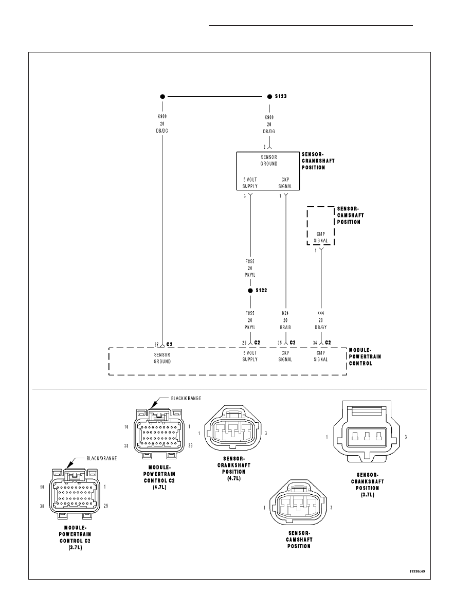
For the Engine circuit diagram (Refer to 9 - ENGINE - SCHEMATICS AND DIAGRAMS).
For a complete wiring diagram Refer to Section 8W.
•
When Monitored:
While cranking the engine and with the engine running.
•
Set Condition:
When the CKP Sensor failure counter reaches 20. One Trip Fault. Three good trips to turn off the MIL.
Possible Causes
(F855) 5-VOLT SUPPLY CIRCUIT OPEN
(F855) 5-VOLT SUPPLY CIRCUIT SHORTED TO GROUND
(K24) CKP SIGNAL CIRCUIT SHORTED TO BATTERY VOLTAGE
(K24) CKP SIGNAL CIRCUIT OPEN
(K24) CKP SIGNAL CIRCUIT SHORTED TO GROUND
(K24) CKP SIGNAL CIRCUIT SHORTED TO THE (F855) 5-VOLT SUPPLY CIRCUIT
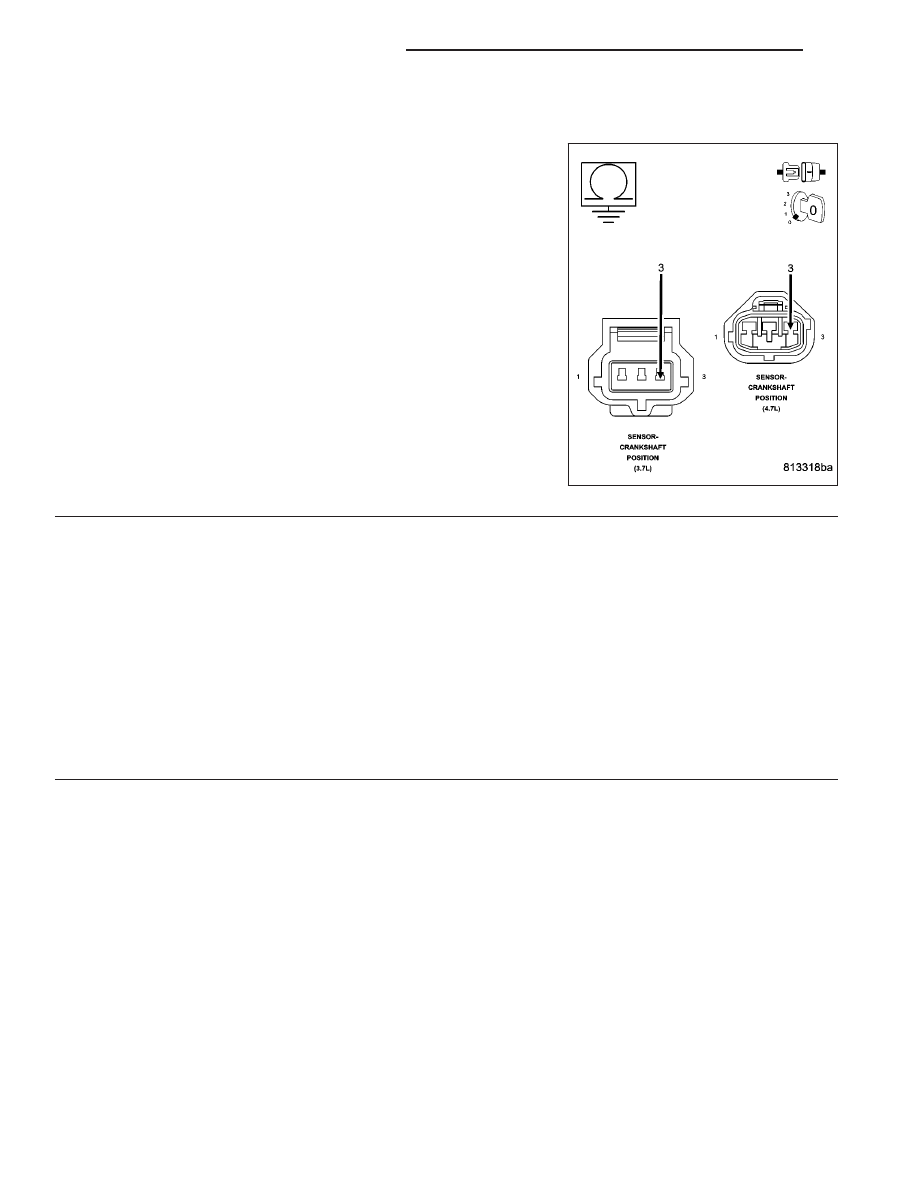
CRANKSHAFT POSITION SENSOR
TONE WHEEL/PULSE RING
PCM
Always perform the Pre-Diagnostic Troubleshooting procedure before proceeding. (Refer to 9 - ENGINE -
DIAGNOSIS AND TESTING).
Diagnostic Test
1.
ACTIVE DTC
Ignition on, engine not running.
With a scan tool read DTCs.
Is the DTC active at this time?
Yes
>> Go To 2
No
>> Refer to the INTERMITTENT CONDITION Diagnostic Procedure.
Perform POWERTRAIN VERIFICATION TEST. (Refer to 9 - ENGINE - STANDARD PROCEDURE)
2.
CHECKING CRANKSHAFT POSITION SENSOR SIGNAL WITH A LAB SCOPE
Turn the ignition off.
With a lab scope probe and the Miller special tool #6801, backprobe the (K24) CKP Signal circuit in the Sensor
harness connector.
WARNING: When the engine is operating, do not stand in direct line with the fan. Do not put your hands
near the pulleys, belts, or fan. Do not wear loose clothing. Failure to follow these instructions can result in
personal injury or death.
Ignition on, engine not running.
Observe the lab scope screen.
Start the engine.
Observe the lab scope screen.
Are there any irregular or missing signals?
Yes
>> Go To 3
No
>> Go To 8
ND
ENGINE ELECTRICAL DIAGNOSTICS
9 - 373
Нет комментариевНе стесняйтесь поделиться с нами вашим ценным мнением.
Текст