Dodge Dakota (ND). Manual — part 845
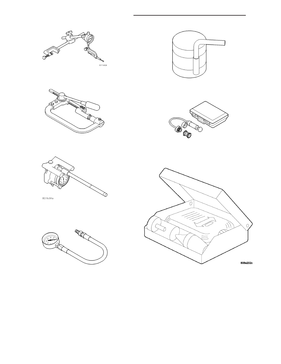
DIAL INDICATOR C-3339
COMPRESSOR VALVE SPRING C-3422-C
INDICATOR CYLINDER BORE C-119
GAUGE OIL PRESSURE - C-3292
Piston Ring Compressor C-385
Pressure Tester Kit 7700
BLOC-CHEK KIT C-3685
9 - 918
ENGINE - 4.7L SERVICE INFORMATION
ND
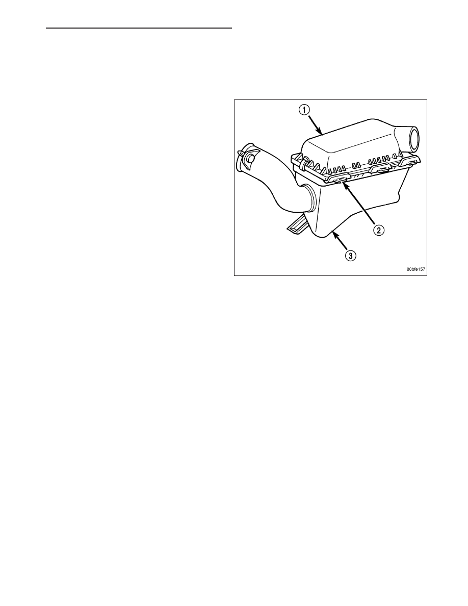
CLEANER-AIR ELEMENT
REMOVAL
Housing removal is not necessary for element (filter) replacement.
1. Pry up spring clips from housing cover (spring clips
retain cover to housing).
2. Release housing cover from locating tabs on hous-
ing and remove cover.
3. Remove air cleaner element (filter) from housing.
4. Clean inside of housing before replacing element.
INSTALLATION
1. Install element into housing.
2. Position housing cover into housing locating tabs.
3. Pry up spring clips and lock cover to housing.
CYLINDER HEAD
DESCRIPTION
DESCRIPTION - CYLINDER HEAD
The cylinder heads are made of an aluminum alloy. The cylinder head features two valves per cylinder with pressed
in powdered metal valve guides. The cylinder heads also provide enclosures for the timing chain drain, necessitating
unique left and right cylinder heads.
DESCRIPTION - VALVE GUIDES
The valve guides are made of powered metal and are pressed into the cylinder head. The guides are not replace-
able or serviceable, and valve guide reaming is not recommended. If the guides are worn beyond acceptable limits,
replace the cylinder heads.
DIAGNOSIS AND TESTING
CYLINDER HEAD GASKET
A cylinder head gasket leak can be located between adjacent cylinders or between a cylinder and the adjacent
water jacket.
Possible indications of the cylinder head gasket leaking between adjacent cylinders are:
•
Loss of engine power
•
Engine misfiring
ND
ENGINE - 4.7L SERVICE INFORMATION
9 - 919
•
Poor fuel economy
Possible indications of the cylinder head gasket leaking between a cylinder and an adjacent water jacket are:
•
Engine overheating
•
Loss of coolant
•
Excessive steam (white smoke) emitting from exhaust
•
Coolant foaming
CYLINDER-TO-CYLINDER LEAKAGE TEST
To determine if an engine cylinder head gasket is leaking between adjacent cylinders, follow the procedures in Cyl-
inder Compression Pressure Test (Refer to 9 - ENGINE - DIAGNOSIS AND TESTING). An engine cylinder head
gasket leaking between adjacent cylinders will result in approximately a 50 - 70% reduction in compression pres-
sure.
CYLINDER-TO-WATER JACKET LEAKAGE TEST
WARNING: USE EXTREME CAUTION WHEN THE ENGINE IS OPERATING WITH COOLANT PRESSURE CAP
REMOVED.
VISUAL TEST METHOD
With the engine cool, remove the coolant pressure cap. Start the engine and allow it to warm up until thermostat
opens.
If a large combustion/compression pressure leak exists, bubbles will be visible in the coolant.
COOLING SYSTEM TESTER METHOD
WARNING: WITH COOLING SYSTEM TESTER IN PLACE, PRESSURE WILL BUILD UP FAST. EXCESSIVE
PRESSURE BUILT UP, BY CONTINUOUS ENGINE OPERATION, MUST BE RELEASED TO A SAFE PRESSURE
POINT. NEVER PERMIT PRESSURE TO EXCEED 138 kPa (20 psi).
Install Cooling System Tester 7700 or equivalent to pressure cap neck. Start the engine and observe the tester’s
pressure gauge. If gauge pulsates with every power stroke of a cylinder a combustion pressure leak is evident.
CHEMICAL TEST METHOD
Combustion leaks into the cooling system can also be checked by using Bloc-Chek Kit C-3685-A or equivalent.
Perform test following the procedures supplied with the tool kit.
REMOVAL
REMOVAL - LEFT CYLINDER HEAD
1. Disconnect the negative cable from the battery.
2. Raise the vehicle on a hoist.
3. Disconnect the exhaust pipe at the left side
exhaust manifold.
4. Drain the engine coolant. Refer to COOLING SYS-
TEM.
5. Lower the vehicle.
6. Remove the intake manifold (Refer to 9 - ENGINE/
MANIFOLDS/INTAKE MANIFOLD - REMOVAL).
7. Remove the master cylinder and booster assembly.
Refer to section 5 brakes.
9 - 920
ENGINE - 4.7L SERVICE INFORMATION
ND
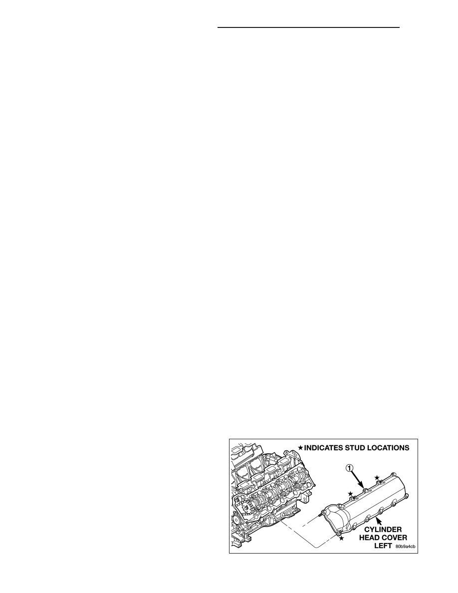
8. Remove the cylinder head cover (Refer to 9 - ENGINE/CYLINDER HEAD/CYLINDER HEAD COVER(S) -
REMOVAL).
9. Remove the fan shroud and fan blade assembly
(Refer to 7 - COOLING/ENGINE/FAN DRIVE VIS-
COUS CLUTCH - REMOVAL).
10. Remove accessory drive belt (Refer to 7 - COOL-
ING/ACCESSORY
DRIVE/DRIVE
BELTS
-
REMOVAL).
11. Remove the power steering pump and set aside.
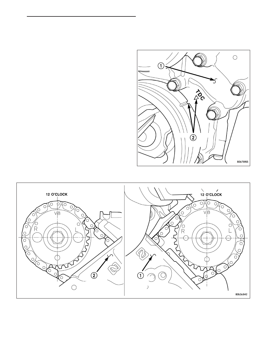
12. Rotate the crankshaft until the damper timing
mark is aligned with TDC indicator mark.
13. Verify the V8 mark on the camshaft sprocket is at the 12 o’clock position. Rotate the crankshaft one turn if
necessary.
14. Remove the crankshaft damper (Refer to 9 - ENGINE/ENGINE BLOCK/VIBRATION DAMPER - REMOVAL).
15. Remove the timing chain cover (Refer to 9 - ENGINE/VALVE TIMING/TIMING BELT / CHAIN COVER(S) -
REMOVAL).
ND
ENGINE - 4.7L SERVICE INFORMATION
9 - 921
Нет комментариевНе стесняйтесь поделиться с нами вашим ценным мнением.
Текст