Dodge Dakota (ND). Manual — part 878
MODULE-FUEL PUMP
DESCRIPTION
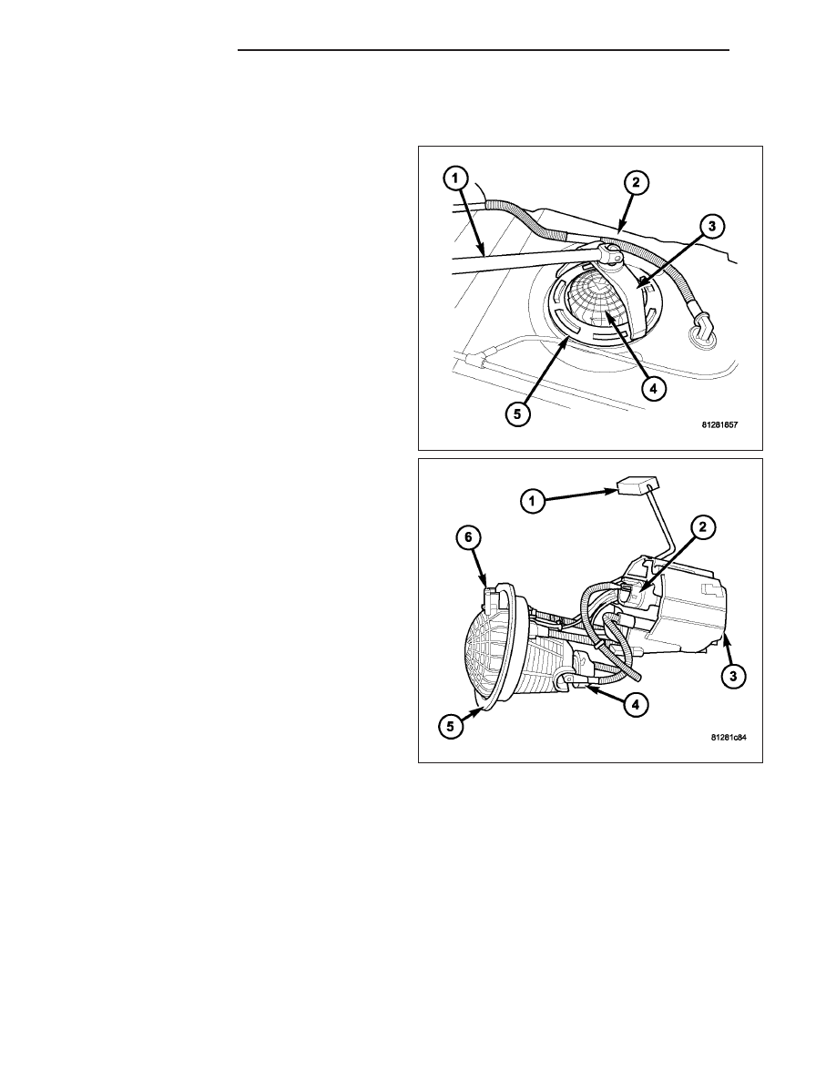
The fuel pump module assembly (4) is located on the
top of the fuel tank (2).
The module assembly (5) contains the following com-
ponents:
•
An internal fuel filter
•
A separate fuel pick-up, or inlet filter (3)
•
A fuel pressure regulator (4)
•
An electric fuel pump (2)
•
A lockring to retain pump module to tank
•
A soft gasket between tank flange and module
•
A fuel gauge sending unit (fuel level sensor) (1)
•
Fuel line connection (6)
If the fuel gauge sending unit , electrical fuel pump,
primary inlet filter, fuel filter or fuel pressure regulator
require service, the fuel pump module must be
replaced.
Electric Fuel Pump
The electric fuel pump is located inside of the fuel pump module. A 12 volt, permanent magnet, electric motor pow-
ers the fuel pump. The electric fuel pump is not a separate, serviceable component.
Fuel Filters
Two fuel filters are used. One is located at the bottom of the fuel pump module. The other is located inside the
module. A separate frame mounted fuel filter is not used with any engine.
Both fuel filters are designed for extended service. They do not require normal scheduled maintenance. Filters
should only be replaced if a diagnostic procedure indicates to do so.
Fuel Pressure Regulator
The fuel pressure regulator is located within fuel pump module.
14 - 10
FUEL DELIVERY
ND
Fuel Gauge Sending Unit (Fuel level sensor)
The fuel gauge sending unit (fuel level sensor) is attached to the side of the fuel pump module. The sending unit
consists of a float, an arm, and a variable resistor track (card).
REMOVAL
WARNING: THE FUEL SYSTEM IS UNDER A CONSTANT PRESSURE (EVEN WITH THE ENGINE OFF).
BEFORE SERVICING THE FUEL PUMP MODULE, THE FUEL SYSTEM PRESSURE MUST BE RELEASED.
1. Drain and remove fuel tank. Refer to Fuel Tank
Removal/Installation.
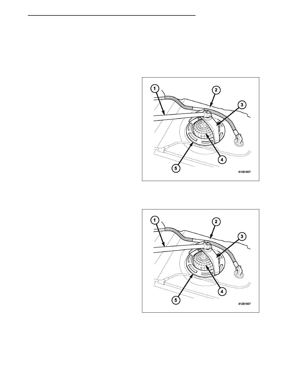
2. Note rotational position of module before attempt-
ing removal. An indexing arrow is located on top of
module for this purpose.
3. Position Special Tool 9340 (3) into notches on out-
side edge of lockring (5).
4. Install 1/2 inch drive breaker bar (1) to tool 9340
(3).
5. Rotate breaker bar counter-clockwise to remove
lockring.
6. Remove lockring. The module will spring up slightly
when lockring is removed.
7. Remove module from fuel tank. Be careful not to
bend float arm while removing.
INSTALLATION
CAUTION: Whenever the fuel pump module is serviced, the rubber seal (gasket) must be replaced.
1. Using a new seal (gasket), position fuel pump mod-
ule into opening in fuel tank.
2. Position lockring (5) over top of fuel pump module.
3. Rotate module until embossed alignment arrow
points to center alignment mark. This step must be
performed to prevent float from contacting side of
fuel tank. Also be sure fuel fitting on top of pump
module is pointed to drivers side of vehicle.
4. Install Special Tool 9340 (3) to lockring.
5. Install 1/2 inch drive breaker (1) into Special Tool
9340 (3).
6. Tighten lockring (clockwise) until all seven notches
have engaged.
7. Install
fuel
tank.
Refer
to
Fuel
Tank
Removal/Installation.
RAIL-FUEL
DESCRIPTION
The fuel injector rail is used to mount the fuel injectors to the engine.
ND
FUEL DELIVERY
14 - 11
OPERATION
High pressure from the fuel pump is routed to the fuel rail. The fuel rail then supplies the necessary fuel to each
individual fuel injector.
A quick-connect fitting with a safety latch clip is used to attach the fuel line to the fuel rail.
The fuel rail is not repairable.
CAUTION: The left and right sections of the fuel rail are connected with either a flexible connecting hose, or
joints. Do not attempt to separate the rail halves at these connecting hose or joints. Due to the design of
the connecting hose or joint, it does not use any clamps. Never attempt to install a clamping device of any
kind to the hose or joint. When removing the fuel rail assembly for any reason, be careful not to bend or
kink the connecting hose or joint.
REMOVAL
3.7L V-6
WARNING: THE FUEL SYSTEM IS UNDER CONSTANT PRESSURE EVEN WITH ENGINE OFF. BEFORE SER-
VICING FUEL RAIL, FUEL SYSTEM PRESSURE MUST BE RELEASED.
CAUTION: The left and right fuel rails are replaced as an assembly. Do not attempt to separate rail halves
at connector tubes. Due to design of tubes, it does not use any clamps. Never attempt to install a clamping
device of any kind to tubes. When removing fuel rail assembly for any reason, be careful not to bend or
kink tubes.
1. Remove fuel tank filler tube cap.
2. Perform Fuel System Pressure Release Procedure.
3. Remove negative battery cable at battery.
4. Remove air duct at throttle body air box.
5. Remove air box at throttle body.
6. Remove air resonator mounting bracket at front of
throttle body (2 bolts).
7. Disconnect fuel line latch clip and fuel line at fuel
rail. A special tool will be necessary for fuel line
disconnection. Refer to Quick-Connect Fittings.
8. Remove necessary vacuum lines at throttle body.
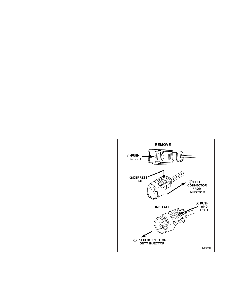
9. Disconnect electrical connectors at all 6 fuel injec-
tors. Refer to graphic. Push red colored slider away
from injector (1). While pushing slider, depress tab
(2) and remove connector (3) from injector. The
factory fuel injection wiring harness is numerically
tagged (INJ 1, INJ 2, etc.) for injector position iden-
tification. If harness is not tagged, note wiring loca-
tion before removal.
10. Disconnect electrical connectors at all throttle
body sensors.
11. Remove 6 ignition coils. Refer to Ignition Coil
Removal/Installation.
14 - 12
FUEL DELIVERY
ND
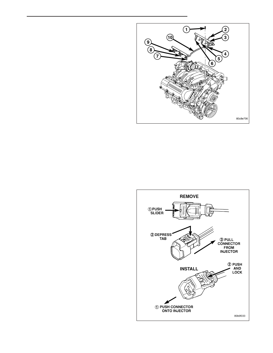
12. Remove four fuel rail mounting bolts (1).
13. Gently rock and pull left side of fuel rail until fuel
injectors just start to clear machined holes in cyl-
inder head. Gently rock and pull right side of rail
until injectors just start to clear cylinder head
holes. Repeat this procedure (left/right) until all
injectors have cleared cylinder head holes.
14. Remove fuel rail (with injectors attached) from
engine.
15. If fuel injectors are to be removed, refer to Fuel
Injector Removal/Installation.
4.7L V-8
WARNING: THE FUEL SYSTEM IS UNDER CONSTANT PRESSURE EVEN WITH ENGINE OFF. BEFORE SER-
VICING FUEL RAIL, FUEL SYSTEM PRESSURE MUST BE RELEASED.
CAUTION: The left and right fuel rails are replaced as an assembly. Do not attempt to separate rail halves
at connector tubes. Due to design of tubes, it does not use any clamps. Never attempt to install a clamping
device of any kind to tubes. When removing fuel rail assembly for any reason, be careful not to bend or
kink tubes.
1. Remove fuel tank filler tube cap.
2. Perform Fuel System Pressure Release Procedure.
3. Remove negative battery cable at battery.
4. Remove air duct at throttle body air box.
5. Remove air box at throttle body.
6. Remove air resonator mounting bracket at front of
throttle body (2 bolts).
7. Disconnect fuel line latch clip and fuel line at fuel
rail. A special tool will be necessary for fuel line
disconnection. Refer to Quick-Connect Fittings.
8. Remove necessary vacuum lines at throttle body.
9. Disconnect electrical connectors at all 8 fuel injec-
tors. Refer to graphic. Push red colored slider away
from injector (1). While pushing slider, depress tab
(2) and remove connector (3) from injector. The
factory fuel injection wiring harness is numerically
tagged (INJ 1, INJ 2, etc.) for injector position iden-
tification. If harness is not tagged, note wiring loca-
tion before removal.
10. Disconnect electrical connectors at all throttle
body sensors.
11. Remove 8 ignition coils. Refer to Ignition Coil
Removal/Installation.
ND
FUEL DELIVERY
14 - 13
Нет комментариевНе стесняйтесь поделиться с нами вашим ценным мнением.
Текст