Dodge Dakota (ND). Manual — part 693
P0305-CYLINDER 5 MISFIRE
9 - 310
ENGINE ELECTRICAL DIAGNOSTICS
ND

P0305-CYLINDER 5 MISFIRE (CONTINUED)
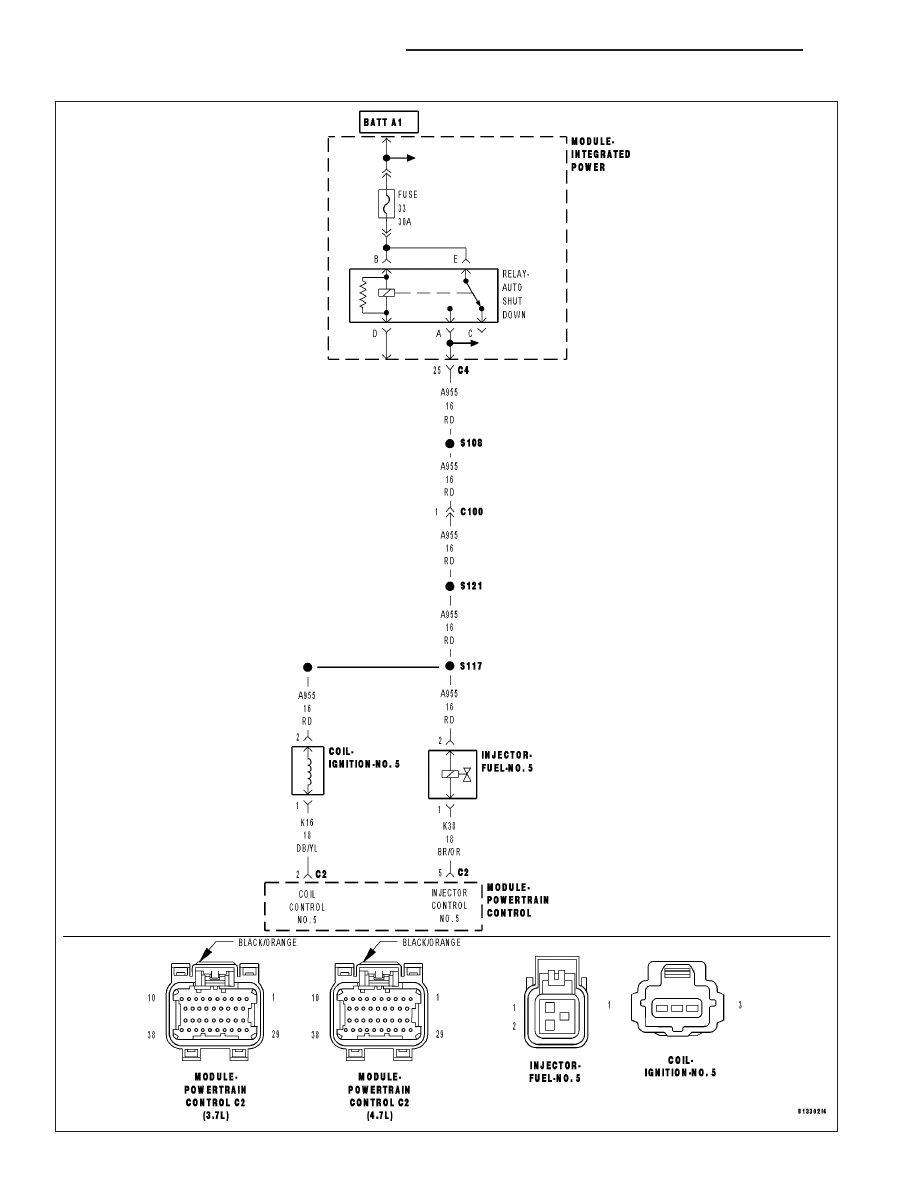
For the Engine circuit diagram (Refer to 9 - ENGINE - SCHEMATICS AND DIAGRAMS).
For a complete wiring diagram Refer to Section 8W.
•
When Monitored:
Any time the engine is running, and the adaptive numerator has been successfully updated.
•
Set Condition:
When more than 2% (2.5%LEV) misfire rate is measured during two trips, or with 10% to 30% misfire rate
during on trip. Three good trips to clear the MIL.
Possible Causes
(A955) ASD RELAY OUTPUT CIRCUIT
(K38) INJECTOR CONTROL NO.5 CIRCUIT
(K16) COIL CONTROL NO.5 CIRCUIT
IGNITION WIRE
SPARK PLUG
IGNITION COIL
FUEL PUMP INLET STRAINER PLUGGED
RESTRICTED FUEL SUPPLY LINE
FUEL PUMP MODULE
FUEL PRESSURE LEAK DOWN
FUEL INJECTOR
ENGINE MECHANICAL PROBLEM
PCM
Always perform the Pre-Diagnostic Troubleshooting procedure before proceeding. (Refer to 9 - ENGINE -
DIAGNOSIS AND TESTING).
Diagnostic Test
1.
CYLINDER MIS-FIRE CONDITION ACTIVE
Engine running.
Observe the WHICH CYLINDER IS MISFIRING screen for at least one minute with a scan tool.
Is there a misfire present at this time?
Yes
>> Go To 2
No
>> Refer to the INTERMITTENT CONDITION Diagnostic Procedure.
Perform POWERTRAIN VERIFICATION TEST. (Refer to 9 - ENGINE - STANDARD PROCEDURE)
ND
ENGINE ELECTRICAL DIAGNOSTICS
9 - 311
P0305-CYLINDER 5 MISFIRE (CONTINUED)
2.
VISUAL INSPECTION
NOTE: Anything that affects the speed of the crankshaft can cause a misfire DTC.
NOTE: When a Misfire is detected for a particular cylinder, the PCM will shut down that cylinders Injector
Control circuit.
- Visually inspect the engine for any of the following conditions.
- Worn serpentine belt
- Binding Engine-Driven accessories: A/C Compressor, P/S Pump, Water pump.
- Misalignment of the Water pump, P/S Pump and A/C Compressor pulleys
- Corroded PCM power and ground circuits.
- Improper CKP, CMP, MAP, and TP Sensor mounting
- Poor connector/terminal to component connection. i.e., CKP sensor, Fuel Injector, Ign coil, etc.
- Vacuum leaks
- Restricted Air Induction system or Exhaust system.
- Internal engine component failures.
Were any of the above conditions present?
Yes
>> Repair as necessary.
Perform POWERTRAIN VERIFICATION TEST. (Refer to 9 - ENGINE - STANDARD PROCEDURE)
No
>> Go To 3
9 - 312
ENGINE ELECTRICAL DIAGNOSTICS
ND
P0305-CYLINDER 5 MISFIRE (CONTINUED)
3.
(A955) ASD RELAY OUTPUT CIRCUIT
Turn the ignition off.
Disconnect the No.5 Ignition Coil harness connector.
Disconnect the No.5 Fuel Injector harness connector.
Ignition on, engine not running.
With the scan tool, actuate the ASD Relay.
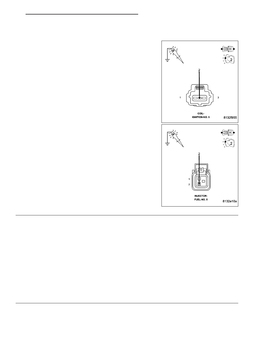
Using a 12-volt test light connected to ground, probe the (A955) ASD
Relay Output circuit in the Ignition Coil harness connector and Fuel
Injector harness connector while the relay is actuating.
Does the test light illuminate brightly?
Yes
>> Go To 4
No
>> Repair the excessive resistance or short to ground in the
(A955) ASD Relay Output circuit.
Perform POWERTRAIN VERIFICATION TEST. (Refer to 9
- ENGINE - STANDARD PROCEDURE)
4.
IGNITION SYSTEM OPERATION
Turn the ignition off.
Connect the Ignition Coil No.5 harness connector.
Remove the Ignition Coil.
Leave the Fuel Injector harness connector of the cylinder being tested disconnected.
Install a spark tester on the Ignition Coil.
While cranking the engine observe the spark coming from the spark tester.
NOTE: A crisp blue spark that is able to jump the gap of the spark tester should be generated.
Is good spark present?
Yes
>> Go To 5
No
>> Go To 14
NOTE: Connect the Fuel Injector harness connector before continuing.
ND
ENGINE ELECTRICAL DIAGNOSTICS
9 - 313
Нет комментариевНе стесняйтесь поделиться с нами вашим ценным мнением.
Текст