Dodge Dakota (ND). Manual — part 858
COVER - STRUCTURAL
DESCRIPTION
The structural dust cover is made of die cast aluminum and joins the lower half of the transmission bell housing to
the engine bedplate.
OPERATION
The structural cover provides additional powertrain stiffness and reduces noise and vibration.
REMOVAL
1. Raise vehicle on hoist.
2. Remove the left hand exhaust pipe from exhaust
manifold.
3. Loosen the right hand exhaust manifold-to-exhaust
pipe retaining bolts.
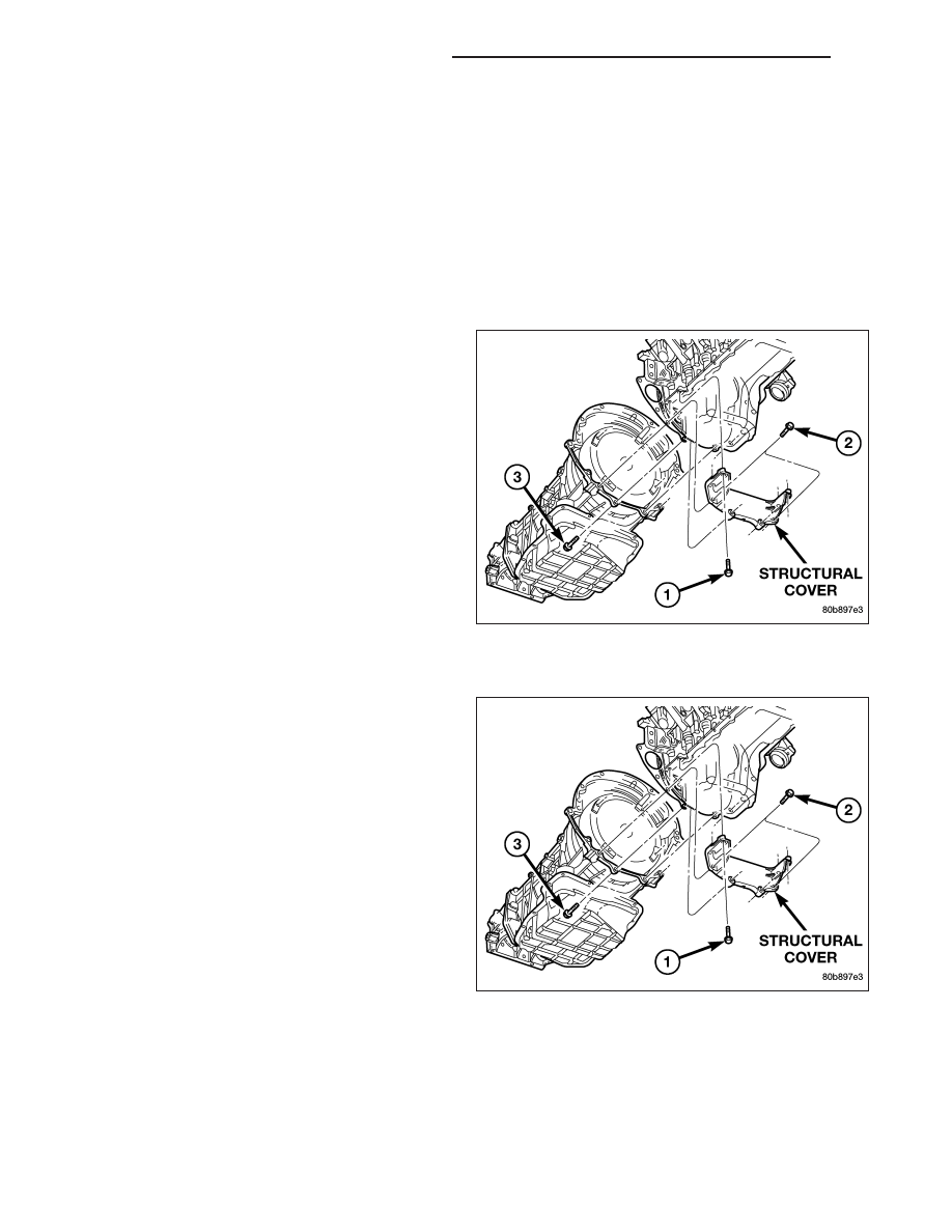
4. Remove the eight bolts (1,2,3) retaining structural
cover in the sequence shown.
5. Pivot the exhaust pipe downward and remove the
structural cover.
INSTALLATION
CAUTION: The structural cover must be installed
as described in the following steps. Failure to do
so will cause severe damage to the cover.
1. Position the structural cover in the vehicle.
2. Install all four bolts retaining the cover-to-engine.
DO NOT tighten the bolts at this time.
3. Install the four cover-to-transmission bolts. Do NOT
tighten at this time.
CAUTION: The structural cover must be held
tightly against both the engine and the transmis-
sion bell housing during tightening sequence. Fail-
ure to do so may cause damage to the cover.
4. Starting with the two rear cover-to-engine bolts,
tighten bolts (1) to 54 N·m (40 ft. lbs.), then tighten bolts (2) and (3) to 54 N·m ( 40 ft. lbs.) in the sequence
shown.
5. Install the exhaust pipe on left hand exhaust manifold.
6. Tighten exhaust manifold-to-exhaust pipe retaining bolts to 20–26 N·m (15–20 ft. lbs.).
9 - 970
ENGINE - 4.7L SERVICE INFORMATION
ND

MOUNT - FRONT
REMOVAL
2WD
1. Disconnect the negative cable from the battery.
CAUTION: Remove the viscous fan before raising engine. Failure to do so may cause damage to the fan
blade, fan clutch and fan shroud.
2. Remove the viscous fan (Refer to 7 - COOLING/ENGINE/FAN DRIVE VISCOUS CLUTCH - REMOVAL).
3. Raise the vehicle.
4. Remove the engine oil filter.
5. Remove the oil drain trough.
6. Support the engine with a suitable jack and a block of wood across the full width of the engine oil pan.
7. Support the front axle with a suitable jack.
8. Remove the bolts that attach the engine mounts to the front axle.
9. Remove the bolts that attach the front axle to the left engine bracket.
10. Lower the front axle.
11. Remove the through bolts
12. Raise the engine far enough to be able to remove the left and right engine mounts.
13. Remove the mount to engine attaching bolts
14. Remove the engine mounts.
4WD
1. Disconnect the negative cable from the battery.
2. Remove the viscous fan.
3. Raise the vehicle.
4. Remove the skid plate.
5. Remove the front crossmember.
6. Remove the engine oil filter.
7. Remove the oil drain trough.
8. Support the engine with a suitable jack and a block
of wood across the full width of the engine oil pan.
9. Support the front axle with a suitable jack.
10. Remove the bolts that attach the engine mounts
to the front axle.
11. Remove the bolts that attach the front axle to the
left engine bracket.
12. Lower the front axle.
13. Remove the through bolts
CAUTION: Remove the viscous fan before raising
engine. Failure to do so may cause damage to the
fan blade, fan clutch and fan shroud.
14. Remove the viscous fan (Refer to 7 - COOLING/ENGINE/FAN DRIVE VISCOUS CLUTCH - REMOVAL).
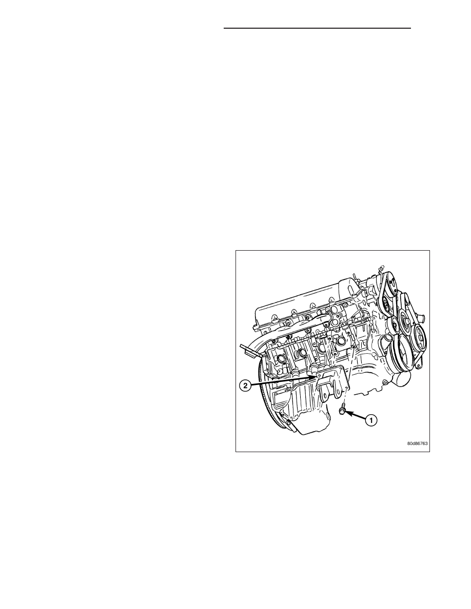
15. Raise the engine far enough to be able to remove the left and right engine mounts (2).
16. Remove the engine mount bolts (1), and the mounts (2).
ND
ENGINE - 4.7L SERVICE INFORMATION
9 - 971
INSTALLATION
2WD
NOTE: For mount to engine block and left engine bracket to front axle bolts, apply Mopar
T
Lock and Seal
Adhesive, Medium Strength Threadlocker.
1. Install the right and left side engine mounts to the engine block bolts. Torque bolts to 54 N·m (40 ft. lbs.).
2. Insert the through bolts into the right and left side engine mounts and loose assemble the two nuts onto the
through bolts.
3. Lower the engine until the through bolts rest onto the slots in the frame brackets.
4. Tighten the through bolt nuts to 94 N·m (70 ft. lbs.).
5. Install the oil drain trough.
6. Install the engine oil filter.
7. Lower the vehicle.
8. Install the viscous fan (Refer to 7 - COOLING/ENGINE/FAN DRIVE VISCOUS CLUTCH - REMOVAL).
9. Reconnect the negative battery cable.
4WD
NOTE: For mount to engine block and left engine
bracket to front axle bolts, apply Mopar
T
Lock and
Seal Adhesive, Medium Strength Threadlocker.
1. Install the right and left side engine mount brackets
(2) to the engine.
2. Install the right and left side engine mounts to the
front axle. Torque nuts to 94 N·m (70 ft. lbs.).
3. Raise the front axle into the frame and install the
left and right side through bolts. Torque nuts to 94
N·m (70 ft. lbs.).
4. Insert the two upper through bolts into the right and
left side engine mounts and loose assemble the
two nuts onto the through bolts.
5. Lower the engine until the left and right side engine
brackets rest on the through bolts, and the lower
engine bracket through holes align with the engine
mounts, and the left engine bracket holes align with
the front axle slots.
6. Loose assemble the bolts that attach the front axle
to the left engine bracket.
7. Loose assemble the lower through bolts.
8. Torque the nuts for the through bolts to 101 N·m (75 ft. lbs.).
9. Torque the bolts that attach the front axle to the left engine bracket to 101 N·m (75 ft. lbs.).
10. Install the oil drain trough.
11. Install the engine oil filter.
12. Lower the vehicle.
13. Install the viscous fan (Refer to 7 - COOLING/ENGINE/FAN DRIVE VISCOUS CLUTCH - REMOVAL).
14. Reconnect the negative battery cable.
9 - 972
ENGINE - 4.7L SERVICE INFORMATION
ND
MOUNT - REAR
REMOVAL
1. Raise the vehicle on a hoist.
2. Using a suitable jack, support transmission.
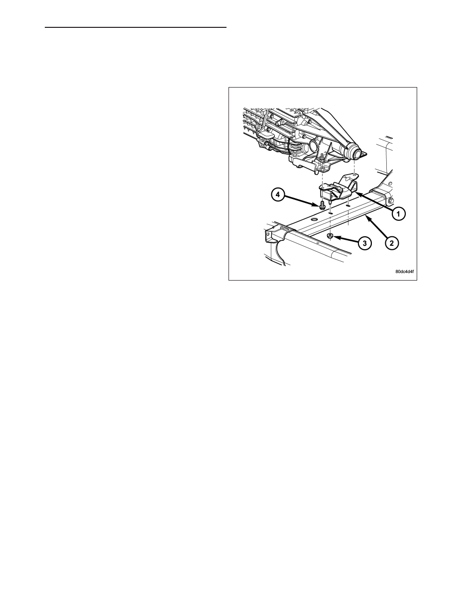
3. Remove the nuts from the transmission mount (1).
4. Remove the two bolts that attach the transmission
mount to the engine bracket.
5. Raise the transmission enough to remove the
mount from the crossmember (2).
6. Remove the mount (1).
INSTALLATION
NOTE: Threadlocking compound must be applied to the bolts before installation.
1. Install the two bolts that attach the transmission mount to the transmission bracket.
2. Torque the bolts to 61N·m (45 ft.lbs.) torque.
3. Lower the transmission so the transmission mount rests on the crossmember, and the studs of the transmission
mount are aligned in the slots in the crossmember.
4. Install the nuts onto the transmission mount studs through the crossmember access slot.
5. Torque the nuts to 54N·m (40 ft. lbs.).
ND
ENGINE - 4.7L SERVICE INFORMATION
9 - 973
Нет комментариевНе стесняйтесь поделиться с нами вашим ценным мнением.
Текст