Dodge Dakota (ND). Manual — part 939
P0755-2/4 SOLENOID CIRCUIT (CONTINUED)
3.
PCM AND WIRING
Turn the ignition off to the lock position.
Remove the Starter Relay.
CAUTION: Removal of the Starter Relay is to prevent a Transmission NO RESPONSE condition and to dis-
able the starter.
Install the Transmission Simulator, Miller tool #8333 and the Electronic Transmission Adapter kit 8333-1A.
Ignition on, engine not running.
With the scan tool, actuate the 2/4 Solenoid.
Monitor the 2/4 Solenoid LED on the Transmission Simulator.
Did the 2/4 Solenoid LED on the Transmission Simulator blink on and off during actuation?
Yes
>> Go To 7
No
>> Go To 4
4.
(T19) 2/4 SOLENOID CONTROL CIRCUIT OPEN
Turn the ignition off to the lock position.
Disconnect the PCM C4 harness connector.
Disconnect the Transmission Solenoid/Pressure Switch Assembly har-
ness connector.
CAUTION: Do not probe the PCM harness connectors. Probing
the PCM harness connectors will damage the PCM terminals
resulting in poor terminal to pin connection. Install Miller Special
Tool #8815 to perform diagnosis.
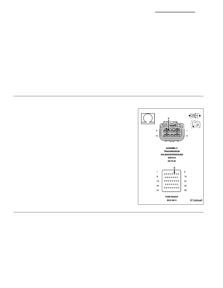
Measure the resistance of the (T19) 2/4 Solenoid Control circuit from
the appropriate terminal of special tool #8815 to the Solenoid/Pressure
Switch Assembly harness connector.
Is the resistance above 5.0 ohms?
Yes
>> Repair the (T19) 2/4 Solenoid Control circuit for an open.
Perform 42RLE TRANSMISSION VERIFICATION TEST -
VER 1.
No
>> Go To 5
21 - 148
AUTOMATIC TRANSMISSION 42RLE - ELECTRICAL DIAGNOSTICS
ND
P0755-2/4 SOLENOID CIRCUIT (CONTINUED)
5.
(T19) 2/4 SOLENOID CONTROL CIRCUIT SHORT TO GROUND
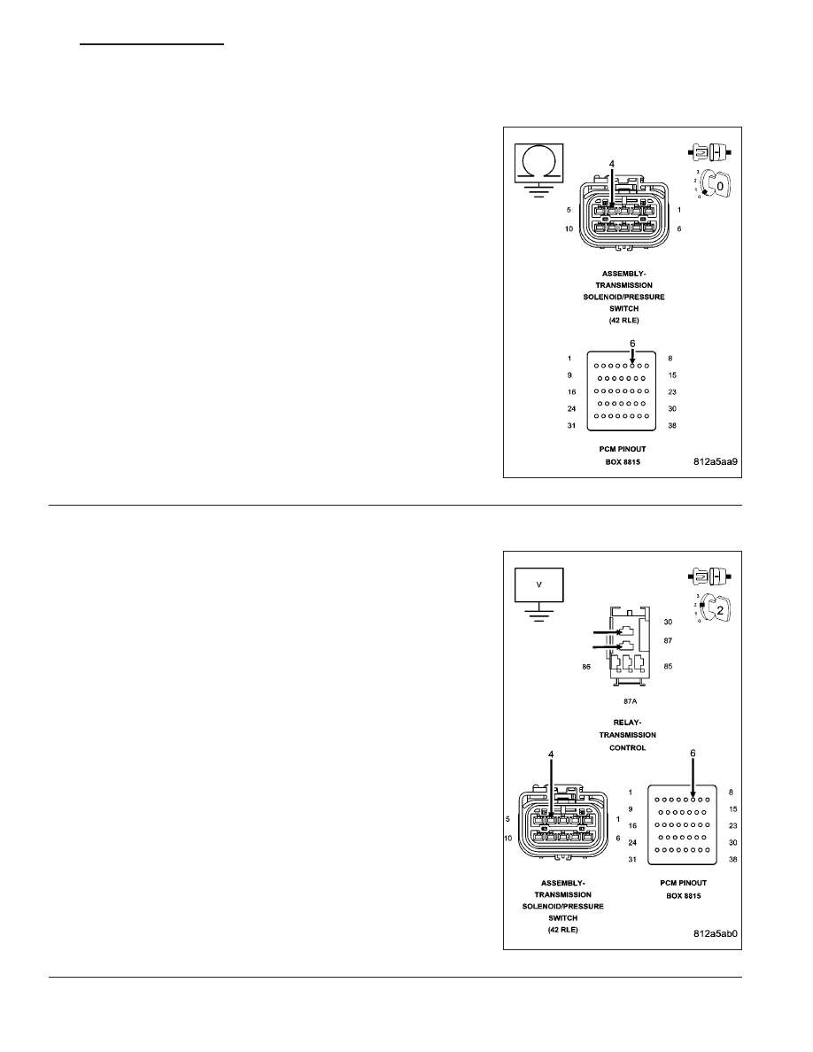
Measure the resistance between ground and the (T19) 2/4 Solenoid
Control circuit.
Is the resistance below 5.0 ohms?
Yes
>> Repair the (T19) 2/4 Solenoid Control circuit for a short to
ground.
Perform 42RLE TRANSMISSION VERIFICATION TEST -
VER 1.
No
>> Go To 6
6.
(T19) 2/4 SOLENOID CONTROL CIRCUIT SHORT TO VOLTAGE
Remove the Transmission Control Relay.
NOTE: Check connectors - Clean/repair as necessary.
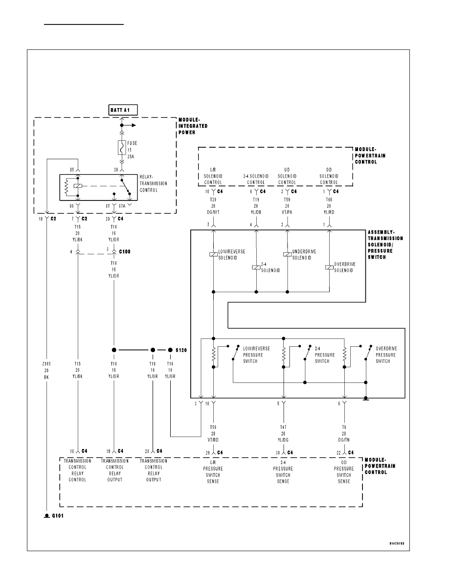
Connect a jumper wire between the (A104) Fused B+ circuit and the
(T16) Transmission Control Relay Output circuit in the Transmission
Control Relay connector.
Ignition on, engine not running.
Measure the voltage of the (T19) 2/4 Solenoid Control circuit.
Is the voltage above 0.5 volts?
Yes
>> Repair the (T19) 2/4 Solenoid Control circuit for a short to
voltage.
Perform 42RLE TRANSMISSION VERIFICATION TEST -
VER 1.
No
>> Go To 8
ND
AUTOMATIC TRANSMISSION 42RLE - ELECTRICAL DIAGNOSTICS
21 - 149
P0755-2/4 SOLENOID CIRCUIT (CONTINUED)
7.
2/4 SOLENOID/PRESSURE SWITCH ASSEMBLY
If there are no possible causes remaining, view repair.
Repair
Replace the Transmission Solenoid/Pressure Switch Assembly per the Service Information.
Perform 42RLE TRANSMISSION VERIFICATION TEST - VER 1.
8.
POWERTRAIN CONTROL MODULE
Using the schematics as a guide, inspect the wiring and connectors. Repair as necessary. Pay particular attention
to all power and ground circuits.
If there are no possible causes remaining, view repair.
Repair
Replace the Powertrain Control Module per the Service Information. With the scan tool perform QUICK
LEARN.
Perform 42RLE TRANSMISSION VERIFICATION TEST - VER 1.
9.
INTERMITTENT WIRING AND CONNECTORS
The conditions necessary to set the DTC are not present at this time.
Using the schematics as a guide, inspect the wiring and connectors specific to this circuit.
Wiggle the wires while checking for shorted and open circuits.
With the scan tool, check the EATX DTC EVENT DATA to help identify the conditions in which the DTC was set.
Were there any problems found?
Yes
>> Repair as necessary.
Perform 42RLE TRANSMISSION VERIFICATION TEST - VER 1.
No
>> Test Complete.
21 - 150
AUTOMATIC TRANSMISSION 42RLE - ELECTRICAL DIAGNOSTICS
ND
P0760-OD SOLENOID CIRCUIT
ND
AUTOMATIC TRANSMISSION 42RLE - ELECTRICAL DIAGNOSTICS
21 - 151
Нет комментариевНе стесняйтесь поделиться с нами вашим ценным мнением.
Текст