Dodge Dakota (ND). Manual — part 502
B2302-WIPER MODE SWITCH INPUT CIRCUIT HIGH (CONTINUED)
For the Wiper/Washer system circuit diagram (Refer to 8 - ELECTRICAL/WIPERS/WASHERS - SCHEMATICS AND
DIAGRAMS).
For a complete wiring diagram Refer to Section 8W.
•
When Monitored:
•
With the ignition on.
•
Set Condition:
•
When the Instrument Cluster detects a short/HIGH condition.
Possible Causes
MULTIFUNCTION SWITCH
(W52) MUX CIRCUIT OPEN
INSTRUMENT CLUSTER
Always perform the Pre-Diagnostic Troubleshooting procedure before proceeding.
Diagnostic Test
1.
INTERMITTENT CONDITION
Turn the ignition on.
With the Scan Tool, clear all CCN DTC’s.
Turn the Wipers ON then OFF.
With the Scan Tool, read the Wiper DTC’s.
Does the Scan Tool read: B2302-WIPER MODE SWITCH INPUT
CIRCUIT HIGH?
Yes
>> Go To 2
No
>> The condition that caused the symptom is currently not
present. Inspect the related wiring for a possible intermit-
tent condition. Look for any chafed, pierced, pinched, or
partially broken wires.
Perform the BODY VERIFICATION TEST — VER 1.
2.
MULTIFUNCTION SWITCH
Turn the ignition off.
Disconnect the Multifunction Switch harness connector.
Ensure the switch is in the OFF position.
Measure the internal resistance of the Multifunction Switch between the G902 and W52 circuits.
Does the Switch measure more than 5.0 ohms?
Yes
>> Replace the Multifunction Switch in accordance with the service information.
Perform the BODY VERIFICATION TEST — VER 1.
No
>> Go To 3
8R - 6
WIPERS/WASHERS - ELECTRICAL DIAGNOSTICS
ND

B2302-WIPER MODE SWITCH INPUT CIRCUIT HIGH (CONTINUED)
3.
INSTRUMENT CLUSTER
Turn the ignition off.
Disconnect the Multifunction Switch connector.
Disconnect the Instrument Cluster C1 harness connector.
Measure the resistance of the (W52) MUX circuit.
Is the resistance above 5.0 ohms?
Yes
>> Repair the (W52) MUX circuit for an open condition.
Perform the BODY VERIFICATION TEST — VER 1.
No
>> Replace the Instrument Cluster in accordance with the ser-
vice information.
Perform the BODY VERIFICATION TEST — VER 1.
ND
WIPERS/WASHERS - ELECTRICAL DIAGNOSTICS
8R - 7
B2304-WIPER PARK SWITCH INPUT CIRCUIT LOW
8R - 8
WIPERS/WASHERS - ELECTRICAL DIAGNOSTICS
ND
B2304-WIPER PARK SWITCH INPUT CIRCUIT LOW (CONTINUED)
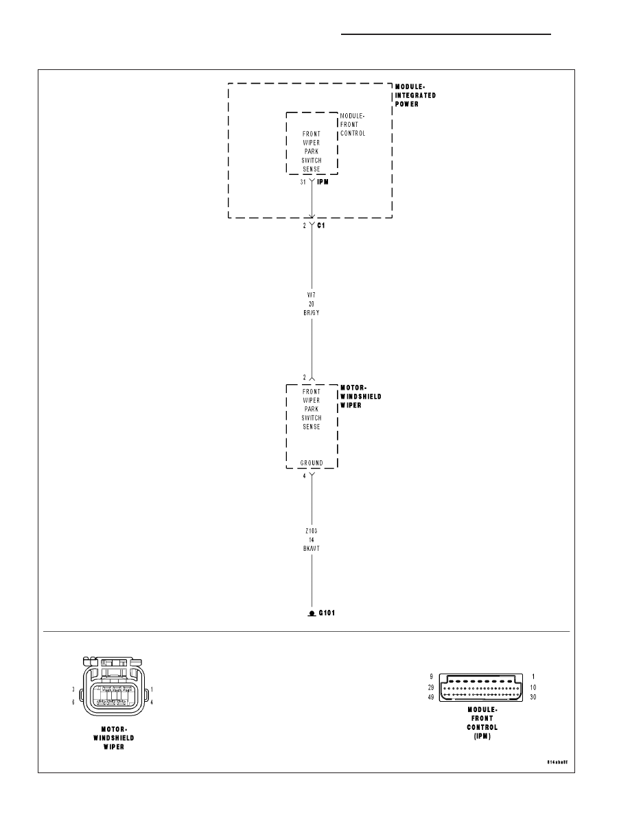
For the Front/Rear Wipers/Washers circuit diagram (Refer to 8 - ELECTRICAL/WIPERS/WASHERS - SCHEMATICS
AND DIAGRAMS).
For a complete wiring diagram Refer to Section 8W.
•
When Monitored:
•
Set Condition:
Possible Causes
MULTIFUNCTION SWITCH
(W7) FRONT WIPER PARK SWITCH SENSE CIRCUIT LOW
FRONT CONTROL MODULE
Always perform the Pre-Diagnostic Troubleshooting procedure before proceeding.
Diagnostic Test
1.
INTERMITTENT CONDITION
Turn the ignition on.
With the Scan Tool, clear all FCM DTC’s.
Turn the Wipers on.
With the Scan Tool, read the Wiper DTC’s.
Does the Scan Tool read: B2304-WIPER PARK SWITCH INPUT
CIRCUIT LOW?
Yes
>> Go To 2
No
>> The condition that caused the symptom is currently not
present. Inspect the related wiring for a possible intermit-
tent condition. Look for any chafed, pierced, pinched, or
partially broken wires.
Perform the BODY VERIFICATION TEST — VER 1.
2.
MULTIFUNCTION SWITCH
Turn the ignition off.
Disconnect the Multifunction Switch connector.
Measure the internal resistance of the Multifunction Switch between cavity 1 and 4 of the switch.
Is the resistance above 5.0 ohms?
Yes
>> Replace the Multifunction Switch in accordance with the service information.
Perform the BODY VERIFICATION TEST — VER 1.
No
>> Go To 3
ND
WIPERS/WASHERS - ELECTRICAL DIAGNOSTICS
8R - 9
Нет комментариевНе стесняйтесь поделиться с нами вашим ценным мнением.
Текст