Dodge Dakota (ND). Manual — part 290
B163C-FRONT LEFT TURN CONTROL CIRCUIT HIGH (CONTINUED)
2.
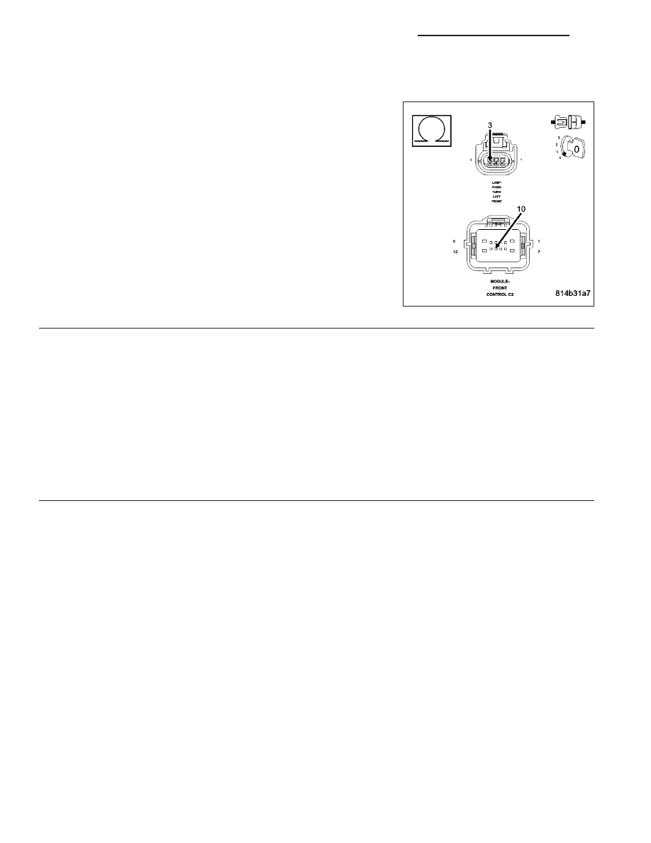
L61 LEFT TURN SIGNAL CONTROL CIRCUIT
Turn the ignition off.
Disconnect the FCM C2 connector.
Measure the resistance of the (L61) Front Left Turn Signal Control cir-
cuit.
Is the resistance above 5.0 ohms?
No
>> Repair the (L61) Turn Signal Control circuit.
Perform BODY VERIFICATION TEST - VER 1.
Yes
>> Go To 3
3.
FRONT CONTROL MODULE
Turn the ignition off.
Disconnect the Front Control Module from the PDC 49-way connector.
Measure the voltage between (L61) Front Left Turn Signal Control circuit and ground.
Is there any voltage present?
Yes
>> Replace the Power Distribution Center in accordance with the service information.
Perform BODY VERIFICATION TEST - VER 1.
No
>> Replace the Front Control Module in accordance with the service information.
Perform BODY VERIFICATION TEST - VER 1.
8L - 22
LAMPS/LIGHTING - EXTERIOR - ELECTRICAL DIAGNOSTICS
ND

B163F-FRONT RIGHT TURN CONTROL CIRCUIT LOW
ND
LAMPS/LIGHTING - EXTERIOR - ELECTRICAL DIAGNOSTICS
8L - 23
B163F-FRONT RIGHT TURN CONTROL CIRCUIT LOW (CONTINUED)
For the Exterior Lighting circuit diagram (Refer to 8 - ELECTRICAL/LAMPS/LIGHTING - EXTERIOR - SCHEMAT-
ICS AND DIAGRAMS).
For a complete wiring diagram Refer to Section 8W.
•
When Monitored:
•
Set Condition:
Possible Causes
(L60) FRONT RIGHT TURN SIGNAL CONTROL CIRCUIT
FRONT CONTROL MODULE
Always perform the Pre-Diagnostic Troubleshooting procedure before proceeding.
Diagnostic Test
1.
INTERMITTENT CONDITION
Turn the ignition on.
With the Scan Tool, clear all FCM DTC’s.
Turn the Right Turn Signals on.
With the Scan Tool read the DTC information.
Does the Scan Tool read: B163F-FRONT RIGHT TURN CON-
TROL CIRCUIT LOW?
Yes
>> Go To 2
No
>> The condition that caused the symptom is currently not
present. Inspect the related wiring for a possible intermit-
tent condition. Look for any chafed, pierced, pinched, or
partially broken wires.
Perform the BODY VERIFICATION TEST - VER 1.
2.
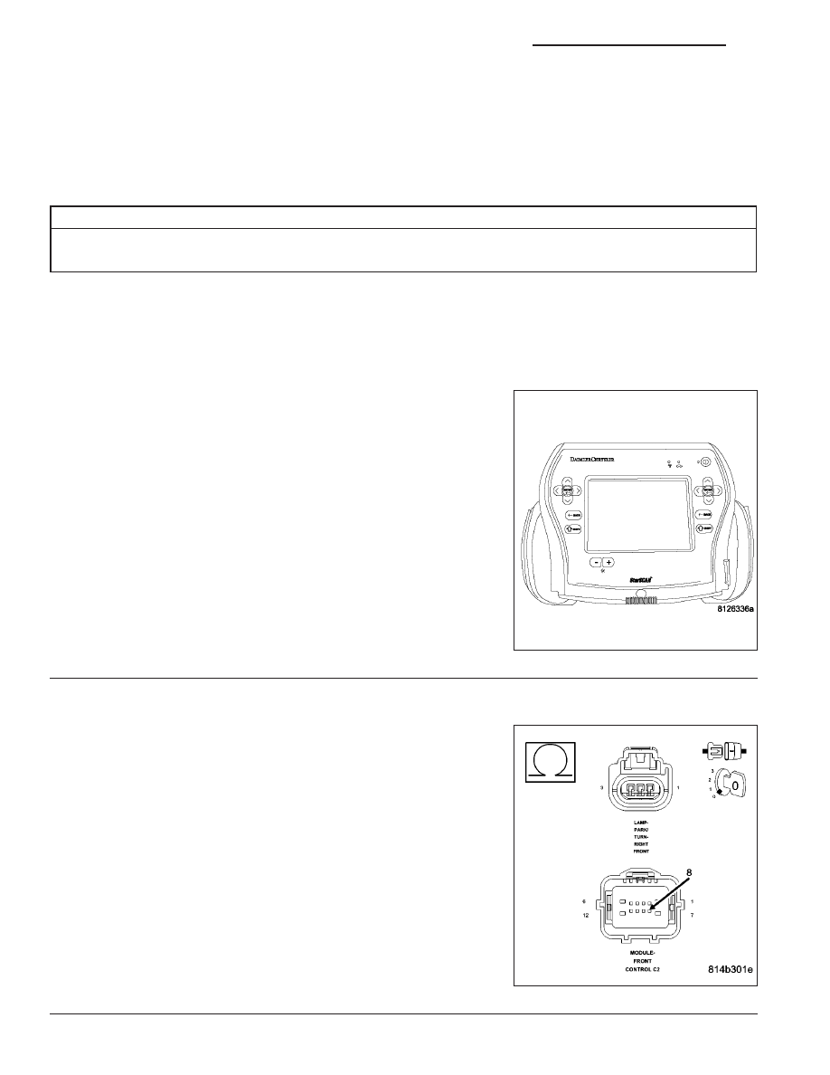
L60 FRONT RIGHT TURN SIGNAL CONTROL CIRCUIT
Turn the ignition off.
Disconnect the FCM C2 harness connector.
Measure the resistance between ground and the (L60) Front Turn Sig-
nal Control circuit.
Is the resistance below 5.0 ohms?
Yes
>> Go To 3
No
>> Repair the (L60) Front Right Turn Signal Control circuit for
a short to ground.
Perform the BODY VERIFICATION TEST - VER 1.
8L - 24
LAMPS/LIGHTING - EXTERIOR - ELECTRICAL DIAGNOSTICS
ND
B163F-FRONT RIGHT TURN CONTROL CIRCUIT LOW (CONTINUED)
3.
FRONT CONTROL MODULE
Turn the ignition off.
Disconnect the FCM connector.
Measure the resistance between ground and the (L60) Front Right Turn Signal Control circuit in the FCM.
Is the resistance below 5.0 ohms?
Yes
>> Replace the Power Distribution Center in accordance with the service information.
Perform the BODY VERIFICATION TEST - VER 1.
No
>> Replace the Front Control Module in accordance with the service information.
Perform the BODY VERIFICATION TEST - VER 1.
ND
LAMPS/LIGHTING - EXTERIOR - ELECTRICAL DIAGNOSTICS
8L - 25
Нет комментариевНе стесняйтесь поделиться с нами вашим ценным мнением.
Текст