Dodge Dakota (ND). Manual — part 327
OVERHEAD CONSOLE - SERVICE INFORMATION
TABLE OF CONTENTS
page
page
OVERHEAD CONSOLE - SERVICE
INFORMATION
DESCRIPTION
. . . . . . . . . . . . . . . . . . . . . . . . . 14
DIAGNOSIS AND TESTING - OVERHEAD
. . . . . . . . . . . . . . . . . . . . . . . . . . . 14
. . . . . . . . . . . . . . . . . 16
. . . . . . . . . . . . . . . . . 17
MODULE-ELECTRONIC OVERHEAD
. . . . . . . . . . . . . . . . . . . . . . . . . 18
. . . . . . . . . . . . . . . . . . . . . . . . . . . 19
. . . . . . . . . . . . . . . 21
. . . . . . . . . . . . . . . . . . . . . . . . . . . . . 24
. . . . . . . . . . . . . . . . . . . . . . . . . 24
UNIVERSAL TRANSMITTER
. . . . . . . . . . . . . . . . . . . . . . . . . 25
. . . . . . . . . . . . . . . . . . . . . . . . . . . 25
REPROGRAMMING TRANSMITTER CODES
SENSOR-AMBIENT AIR TEMPERATURE
. . . . . . . . . . . . . . . . . . . . . . . . . 28
. . . . . . . . . . . . . . . . . . . . . . . . . . . 28
. . . . . . . . . . . . . . . . . . . . . . . . . . . . . 29
. . . . . . . . . . . . . . . . . . . . . . . . . 30
OVERHEAD CONSOLE - SERVICE INFORMATION
DESCRIPTION
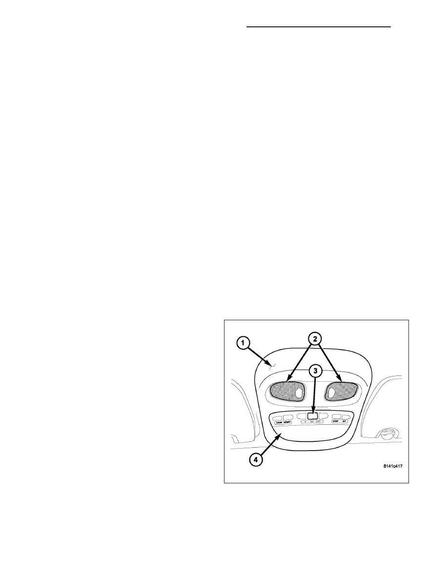
An overhead console (1) is standard on this vehicle
and includes the following components:
•
Front map/reading lamps (2)
•
Electronic Overhead Module (EOM)
The EOM consists of the trip computer with a blue-
green vacuum-fluorescent display screen (4) and the
Universal Transmitter (3). The overhead console
assembly is mounted by two snap clips and one screw
securing it to a molded plastic retainer bracket located
above the headliner. The EOM is secured to the over-
head console with four screws.
DIAGNOSIS AND TESTING - OVERHEAD CONSOLE
NOTE: The overhead console data is obtained from several components on the Controller Area Network
(CAN) Data Bus circuit. The overhead console will not function properly if the bus messages from any of
these components is not receive. If no overhead console data is displayed, check the CAN Data Bus circuit
communications, the Instrument Cluster functions and the Front Control Module (FCM).
8M - 14
OVERHEAD CONSOLE - SERVICE INFORMATION
ND
The most reliable, efficient, and accurate means to diagnose the overhead console or related system requires the
use of a scan tool and the appropriate diagnostic information. The scan tool can provide vital information to find a
problem with a overhead console component. Diagnostic logic is built into the Electronic Overhead Module (EOM) to
help locate the problem by the most efficient means possible. Anytime a problem is suspected, a scan tool must be
used to retrieve any stored fault codes in the EOM. If diagnostic fault codes are present in the module, record them
on a piece of paper immediately before proceeding any further. Then, use these fault codes to identify the problem
by verifying the fault code. Example, If the EOM records “B1034 - INFRARED TEMPERATURE SENSOR INPUT
CIRCUIT LOW” fault, locate the diagnostic procedure for this code in the appropriate diagnostic information and
follow the flow chart until the specific problem is located and resolved. Once the problem is thought to be corrected,
erase the stored fault code using the scan tool and verify correct system operation. If the temperature reading is
functioning correctly, verify that there are no other stored codes in the module and return the vehicle to service.
If the fault code could not be verified, such as not finding anything wrong when following the diagnostic flow chart
in the appropriate diagnostic information. This is a good indication that an INTERMITTENT problem may be present.
You must than attempt to find the intermittent problem, such as loose or corroded wire connections, shorted wire
harnesses, or similar wiring problems. Always, eliminate all other potential problems before attempting to replace the
EOM.
For complete circuit diagrams, refer to the appropriate wiring information. The wiring information includes wir-
ing diagrams, proper wire and connector repair procedures, details of wire harness routing and retention, connector
pin-out information and location views for the various wire harness connectors, splices and grounds.
TESTING VOLTAGE AND GROUND SUPPLY TO OVERHEAD CONSOLE
1. Remove the overhead console from the headliner (Refer to 8 - ELECTRICAL/OVERHEAD CONSOLE -
REMOVAL). Disconnect the overhead console electrical connector. Check the fused B(+) circuit in the overhead
console electrical connector. If OK, go to Step 2. If not OK, repair the open circuit or component as required.
2. Check the IGN RUN B(+) circuit in the overhead console electrical connector. If OK, go to Step 3. If not OK,
repair the open IGN RUN B(+) circuit as required.
3. Check the Ground circuit in the overhead console electrical connector. If OK, go to the appropriate diagnostic
information for final diagnosis. If not OK, repair the open ground circuit as required.
NOTE: If the compass functions, but accuracy is suspect, it may be necessary to perform a variation adjust-
ment. This procedure allows the compass unit to accommodate variations in the earth’s magnetic field
strength, based on geographic location. (Refer to 8 - ELECTRICAL/OVERHEAD CONSOLE/COMPASS/MINI-
TRIP COMPUTER - STANDARD PROCEDURE - COMPASS VARIATION ADJUSTMENT).
ND
OVERHEAD CONSOLE - SERVICE INFORMATION
8M - 15
NOTE: If the compass reading displays dashes, and only “CAL” appears in the display, demagnetizing may
be necessary to remove excessive residual magnetic fields from the vehicle. (Refer to 8 - ELECTRICAL/
OVERHEAD
CONSOLE/COMPASS/MINI-TRIP
COMPUTER
-
STANDARD
PROCEDURE
-
COMPASS
DEMAGNETIZING).
REMOVAL
OVERHEAD CONSOLE
1. Disconnect and isolate the battery negative cable.
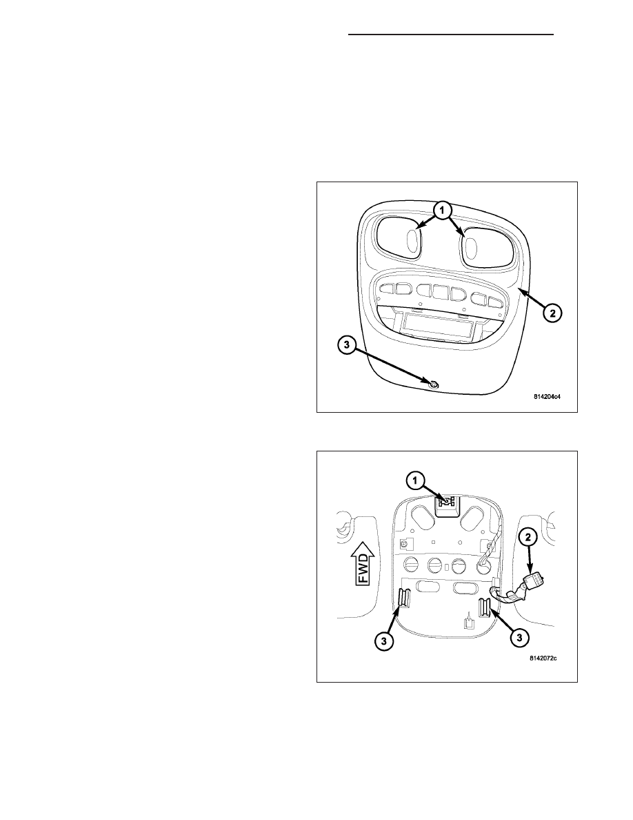
2. Remove the overhead console retaining screw (3),
located in the front of console near the windshield.
3. Using your fingertips, grasp the sides of the over-
head console (2) and pull straight down evenly to
disengage the two snap clips at the rear of the unit.
4. Lower the overhead console from the headliner far
enough to access the wire harness connector (2).
5. Disconnect the roof wire harness connector (2)
from the electronic overhead module.
6. Remove the overhead console from the vehicle.
8M - 16
OVERHEAD CONSOLE - SERVICE INFORMATION
ND
INSTALLATION
OVERHEAD CONSOLE
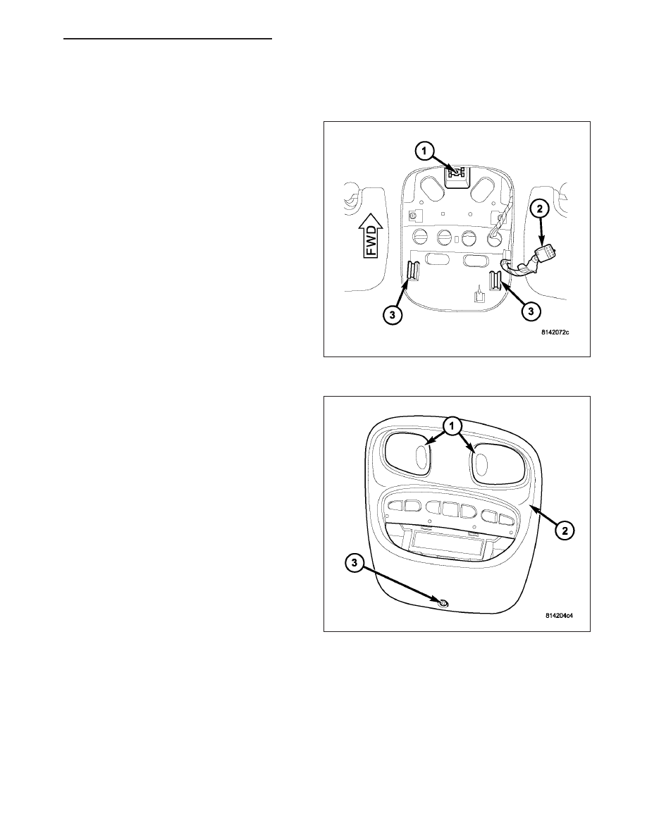
1. Position the overhead console near the mounting
location on the headliner.
2. Reconnect the roof wire harness connector (2) to
the electronic overhead module.
3. Align the snap clips on the overhead console hous-
ing with their receptacles (3) in the overhead con-
sole bracket.
4. Push upward firmly and evenly on the sides of the
overhead console housing over the snap clip loca-
tions until the snap clips are fully engaged with the
receptacles in the overhead console bracket.
5. Install the overhead console retaining screw (3),
located in the front of console near the windshield.
6. Reconnect the battery negative cable.
ND
OVERHEAD CONSOLE - SERVICE INFORMATION
8M - 17
Нет комментариевНе стесняйтесь поделиться с нами вашим ценным мнением.
Текст