Dodge Dakota (ND). Manual — part 505
B2313-WIPER ON/OFF CONTROL CIRCUIT LOW (CONTINUED)
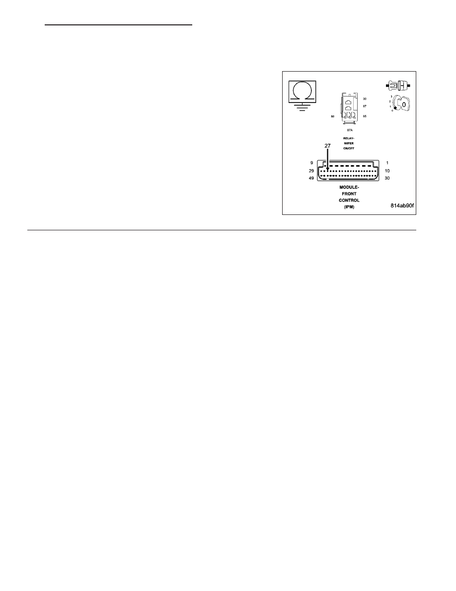
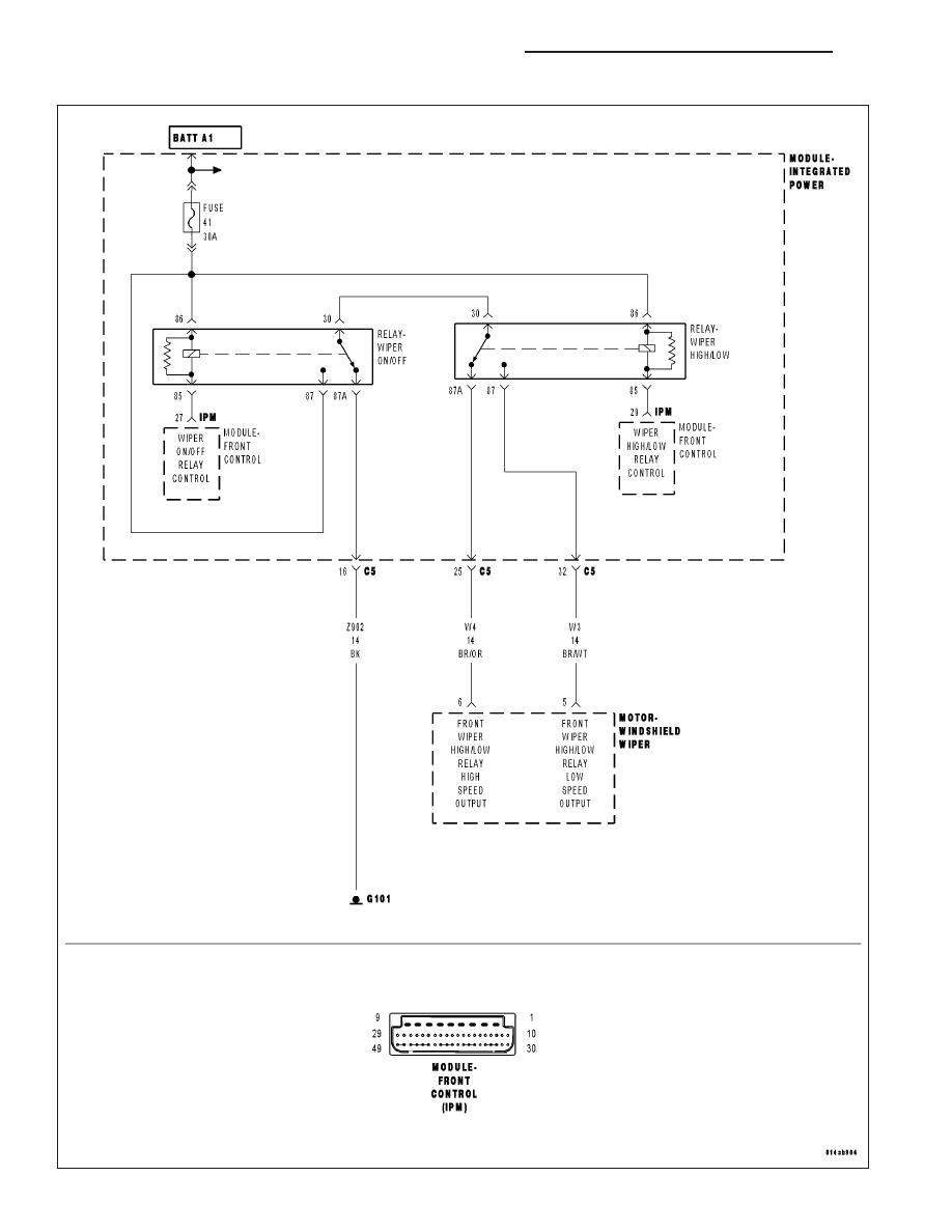
For the Wiper/Washer system circuit diagram (Refer to 8 - ELECTRICAL/WIPERS/WASHERS - SCHEMATICS AND
DIAGRAMS).
For a complete wiring diagram Refer to Section 8W.
•
When Monitored:
•
With the ignition on.
•
Set Condition:
•
When the FCM detects a short/low condition.
Possible Causes
WIPER ON/OFF RELAY
POWER DISTRIBUTION CENTER
FRONT CONTROL MODULE
Always perform the Pre-Diagnostic Troubleshooting procedure before proceeding.
Diagnostic Test
1.
INTERMITTENT CONDITION
Turn the ignition on.
With the Scan Tool, clear all FCM DTC’s.
Turn the Wipers ON then OFF.
With the Scan Tool, read the Wiper DTC’s.
Does the Scan Tool read: B2313-WIPER ON/OFF CONTROL CIR-
CUIT LOW?
Yes
>> Go To 2
No
>> The condition that caused the symptom is currently not
present. Inspect the related wiring for a possible intermit-
tent condition. Look for any chafed, pierced, pinched, or
partially broken wires.
Perform the BODY VERIFICATION TEST — VER 1.
2.
WIPER ON/OFF RELAY
Turn the ignition off.
Install a substitute relay in place of the Wiper On/Off Relay.
Turn the ignition on.
With the Scan Tool, read the DTC’s.
Does the Scan Tool read: B2313-WIPER ON/OFF CONTROL CIRCUIT LOW?
Yes
>> Go To 3
No
>> Replace the Wiper On/Off Relay in accordance with the service information.
Perform the BODY VERIFICATION TEST — VER 1.
8R - 18
WIPERS/WASHERS - ELECTRICAL DIAGNOSTICS
ND
B2313-WIPER ON/OFF CONTROL CIRCUIT LOW (CONTINUED)
3.
Front Control Module
Turn the ignition off.
Remove the Wiper On/Off Relay.
Disconnect the FCM IPM harness connector.
Measure the resistance between ground and the (W5) Wiper On/Off
Relay Control circuit in the PDC.
Is the resistance below 5.0 ohms?
Yes
>> Replace the Power Distribution Center in accordance with
the service information.
Perform the BODY VERIFICATION TEST — VER 1.
No
>> Replace the Front Control Module in accordance with the
service information.
Perform the BODY VERIFICATION TEST — VER 1.
ND
WIPERS/WASHERS - ELECTRICAL DIAGNOSTICS
8R - 19
B2314-WIPER ON/OFF CONTROL CIRCUIT HIGH
8R - 20
WIPERS/WASHERS - ELECTRICAL DIAGNOSTICS
ND
B2314-WIPER ON/OFF CONTROL CIRCUIT HIGH (CONTINUED)
For the Wiper/Washer system circuit diagram (Refer to 8 - ELECTRICAL/WIPERS/WASHERS - SCHEMATICS AND
DIAGRAMS).
For a complete wiring diagram Refer to Section 8W.
•
When Monitored:
•
With the ignition on.
•
Set Condition:
•
When the FCM detects a short/HIGH condition.
Possible Causes
WIPER ON/OFF RELAY
POWER DISTRIBUTION CENTER
FRONT CONTROL MODULE
Always perform the Pre-Diagnostic Troubleshooting procedure before proceeding.
Diagnostic Test
1.
INTERMITTENT CONDITION
Turn the ignition on.
With the Scan Tool, clear all FCM DTC’s.
Turn the Wipers ON then OFF.
With the Scan Tool, read the Wiper DTC’s.
Does the Scan Tool read: B2314-WIPER ON/OFF CONTROL CIR-
CUIT HIGH?
Yes
>> Go To 2
No
>> The condition that caused the symptom is currently not
present. Inspect the related wiring for a possible intermit-
tent condition. Look for any chafed, pierced, pinched, or
partially broken wires.
Perform the BODY VERIFICATION TEST — VER 1.
2.
WIPER ON/OFF RELAY
Turn the ignition off.
Remove the Wiper On/Off Relay.
Turn the ignition on.
Activate the Wiper Switch to all speed positions.
With the Scan Tool, read the DTC’s.
Does the Scan Tool read: B2314-WIPER ON/OFF CONTROL CIRCUIT HIGH?
Yes
>> Replace the Wiper On/Off Relay in accordance with the service information.
Perform the BODY VERIFICATION TEST — VER 1.
No
>> Go To 3
ND
WIPERS/WASHERS - ELECTRICAL DIAGNOSTICS
8R - 21
Нет комментариевНе стесняйтесь поделиться с нами вашим ценным мнением.
Текст