Dodge Dakota (ND). Manual — part 460
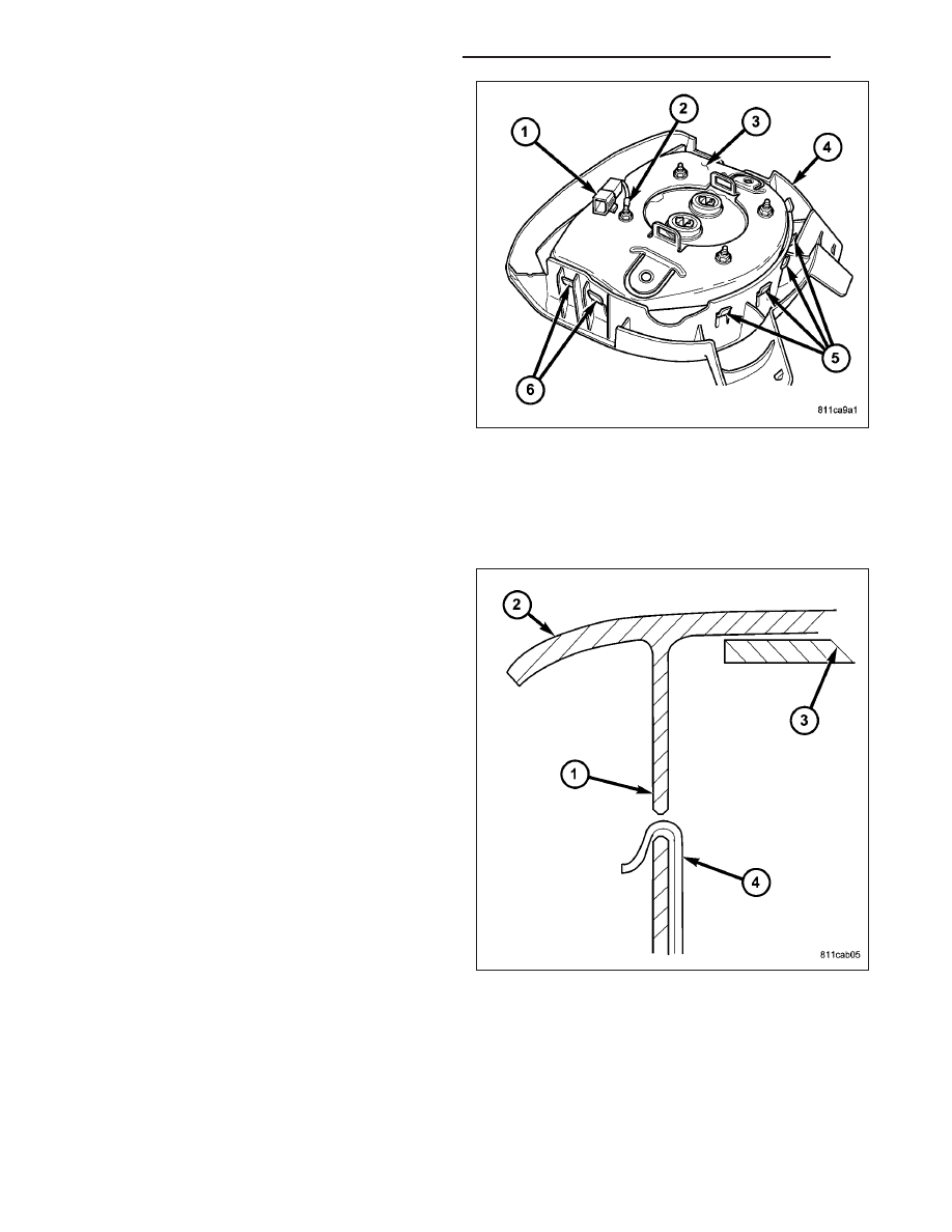
5. Be certain that the horn switch feed and ground
pigtail wires are routed through the clearance notch
at the top of the airbag housing (3), between the
housing and the upper vertical wall of the trim
cover receptacle.
6. Work around the perimeter of the unit engaging
each of the twelve hooks (5 and 6) on the driver
airbag housing through the windows in the walls of
the trim cover receptacle.
7. Install the horn switch ground pigtail wire eyelet ter-
minal (2) over the upper right inflator stud on the
back of the driver airbag housing.
8. Install and tighten the nut that secures the horn
switch ground pigtail wire eyelet terminal to the
upper right inflator stud on the back of the driver
airbag housing. Tighten the nut to 7 N·m (65 in.
lbs.).
9. Using hand pressure, push the integral retainer of
the horn switch feed pigtail wire connector (1) into the locator hole just above the upper right inflator mounting
stud on the back of the airbag housing.
10. After the driver airbag has been assembled, try pulling the trim cover and the airbag housing away from each
other. This action will fully seat the edges of the windows into the cradles of the hooks.
11. Before reinstalling the airbag onto the steering
wheel, check that the blocking tab (1) in each of
the trim cover windows is oriented over the airbag
housing hook (4) as shown.
12. Reinstall the driver airbag onto the steering wheel
(Refer
to
8
-
ELECTRICAL/RESTRAINTS/
DRIVER AIRBAG - INSTALLATION).
INSTALLATION
WARNING: To avoid personal injury or death, on vehicles equipped with airbags, disable the supplemental
restraint system before attempting any steering wheel, steering column, airbag, occupant classification sys-
tem, seat belt tensioner, impact sensor, or instrument panel component diagnosis or service. Disconnect
and isolate the battery negative (ground) cable, then wait two minutes for the system capacitor to discharge
before performing further diagnosis or service. This is the only sure way to disable the supplemental
restraint system. Failure to take the proper precautions could result in accidental airbag deployment.
8O - 436
RESTRAINTS - SERVICE INFORMATION
ND
WARNING: To avoid personal injury or death, use extreme care to prevent any foreign material from enter-
ing the driver airbag, or becoming entrapped between the driver airbag cushion and the driver airbag trim
cover. Failure to observe this warning could result in occupant injuries upon airbag deployment.
WARNING: To avoid personal injury or death, the driver airbag trim cover must never be painted. Replace-
ment airbags are serviced with trim covers in the original colors. Paint may change the way in which the
material of the trim cover responds to an airbag deployment. Failure to observe this warning could result in
occupant injuries upon airbag deployment.
NOTE: The following procedure is for replacement of a faulty or damaged driver airbag. If the airbag is
faulty or damaged, but not deployed, review the recommended procedures for handling non-deployed sup-
plemental restraints. (Refer to 8 - ELECTRICAL/RESTRAINTS - STANDARD PROCEDURE - HANDLING NON-
DEPLOYED
SUPPLEMENTAL
RESTRAINTS).
If
the
driver
airbag
has
been
deployed,
review
the
recommended procedures for service after a supplemental restraint deployment before removing the airbag
from the vehicle. (Refer to 8 - ELECTRICAL/RESTRAINTS - STANDARD PROCEDURE - SERVICE AFTER A
SUPPLEMENTAL RESTRAINT DEPLOYMENT).
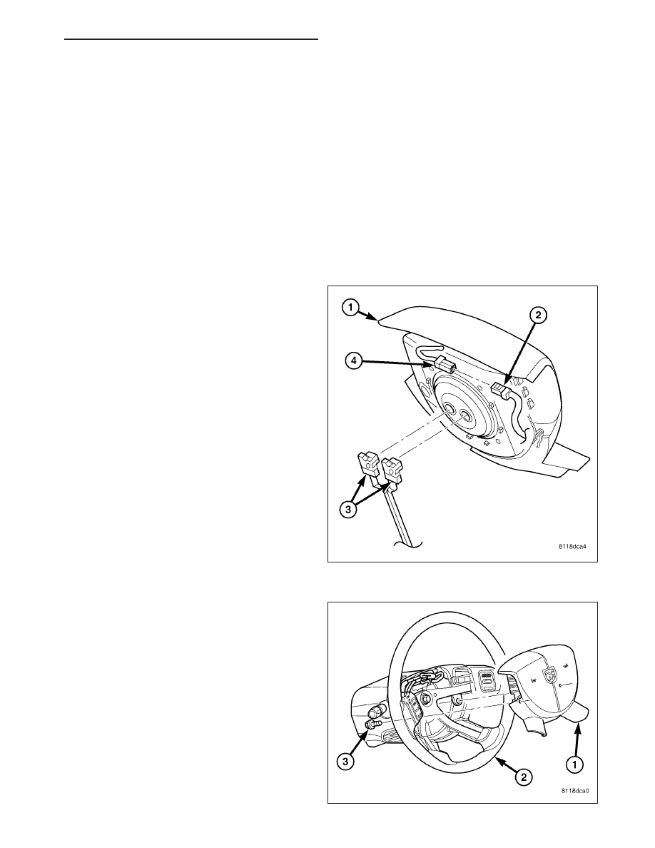
1. Position the driver airbag (1) close enough to the
steering wheel to reconnect the three electrical
connections on the back of the airbag housing.
2. When installing the driver airbag, reconnect the two
clockspring driver airbag pigtail wire connectors (3)
to the airbag inflator connector receptacles by
pressing straight in on the connector. Be certain to
engage each keyed and color-coded connector to
the matching connector receptacle. You can be cer-
tain that each connector is fully engaged in its
receptacle by listening carefully for a distinct, audi-
ble click as the connector latches snap into place.
3. Reconnect the steering wheel wire harness con-
nector (2) for the horn switch to the horn switch
feed pigtail wire connector (4), which is located on
the back of the driver airbag housing.
4. Carefully position the driver airbag (1) in the steer-
ing wheel (2). Be certain that the clockspring pigtail
wires and the steering wheel wire harness in the
steering wheel hub area are not pinched between
the driver airbag and the steering wheel armature.
5. From the underside of the steering wheel, install
and tighten the two screws (3) that secure the
driver airbag to the steering wheel armature.
Tighten the screws to 10 N·m (90 in. lbs.).
6. Do not reconnect the battery negative cable at this
time. The supplemental restraint system verification
test procedure should be performed following ser-
vice of any supplemental restraint system compo-
nent. (Refer to 8 - ELECTRICAL/RESTRAINTS -
STANDARD
PROCEDURE
-
VERIFICATION
TEST).
ND
RESTRAINTS - SERVICE INFORMATION
8O - 437
IMPACT SENSOR
DESCRIPTION
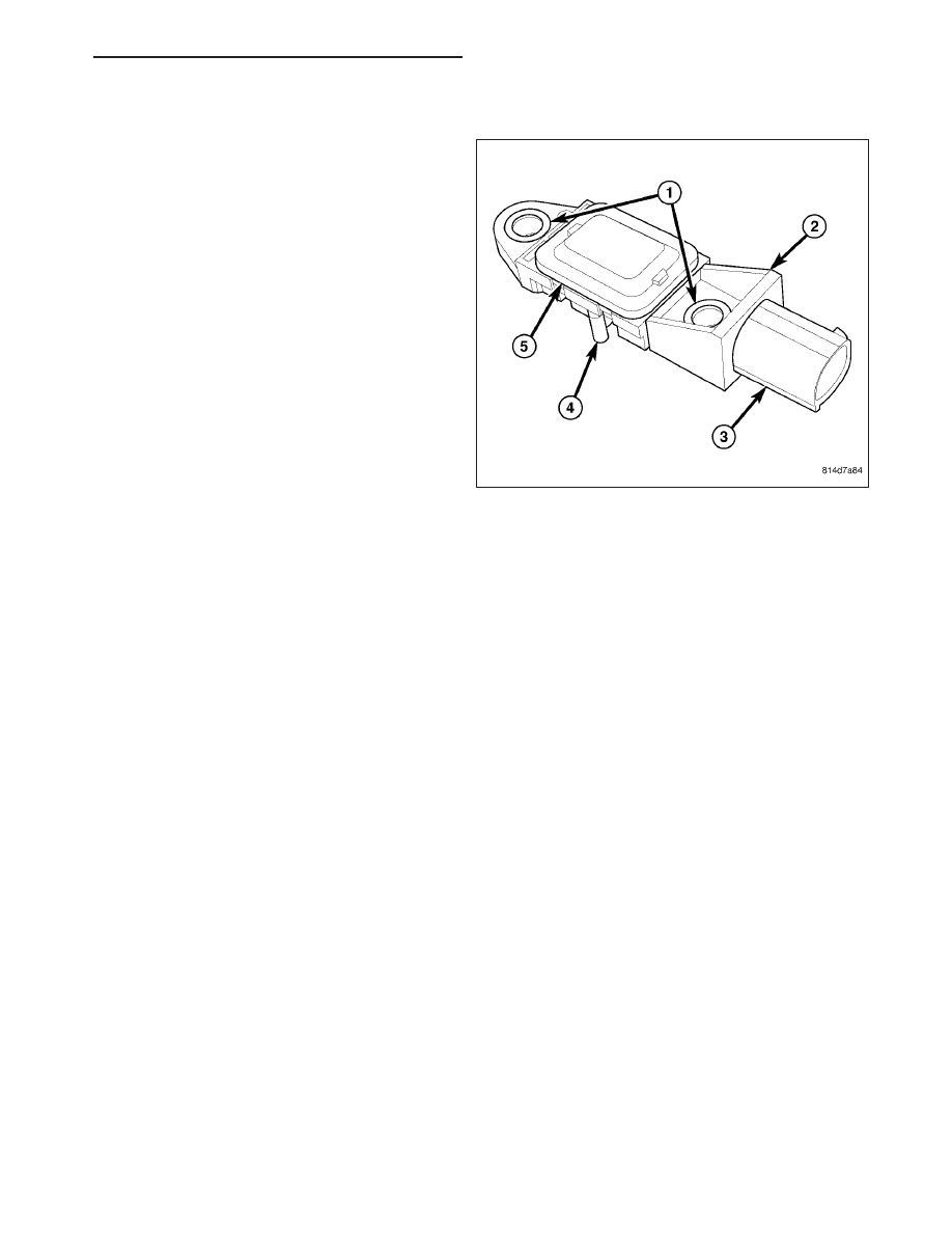
FRONT
Two front impact sensors (1) are used on this model,
one each for the left and right sides of the vehicle.
These sensors are mounted remotely from the impact
sensor that is internal to the Occupant Restraint Con-
troller (ORC). Each front sensor is secured with two
screws to the backs of the right and left vertical mem-
bers of the radiator support within the engine compart-
ment. The sensor housing has an integral connector
receptacle (2), an integral anti-rotation pin (3), and two
integral mounting holes (4) with metal sleeves to pro-
vide crush protection.
The right and left front impact sensors are identical in construction and calibration. A label on the sensor is imprinted
with an arrow, which should always be pointed forward in the vehicle. A cavity in the center of the molded plastic
impact sensor housing contains the electronic circuitry of the sensor which includes an electronic communication
chip and an electronic impact sensor. Potting material fills the cavity and a stamped cover (5) is crimped over the
cavity to seal and protect the internal electronic circuitry and components. The front impact sensors are each con-
nected to the vehicle electrical system through a dedicated take out and connector of the headlamp and dash wire
harness.
The impact sensors cannot be repaired or adjusted and, if damaged or faulty, they must be replaced.
8O - 438
RESTRAINTS - SERVICE INFORMATION
ND
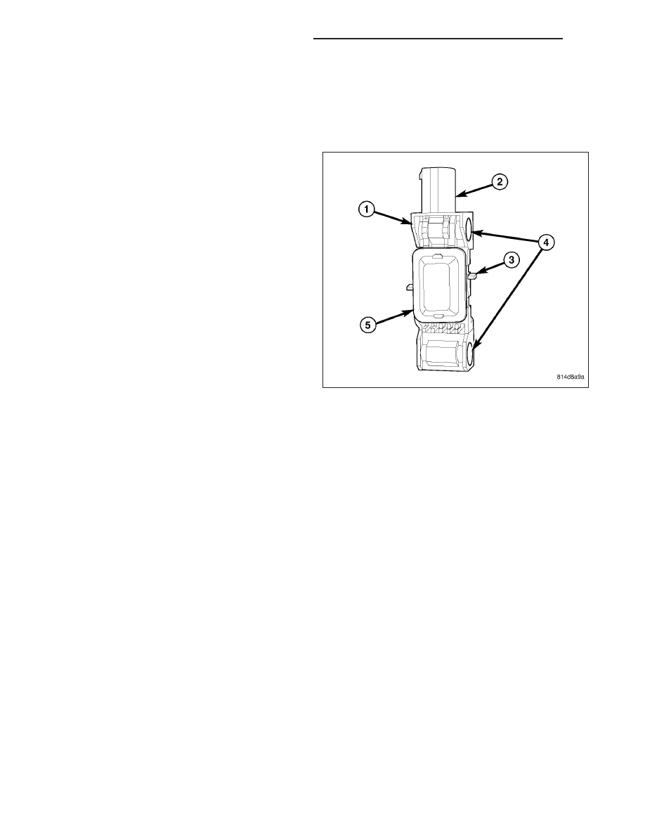
SIDE
Two side impact sensors (2) are used on this model
when it is equipped with the optional side curtain air-
bags, one each for the left and right sides of the vehi-
cle. These sensors are mounted remotely from the
impact
sensor
that
is
internal
to
the
Occupant
Restraint Controller (ORC). Each side sensor is
secured with two screws to the floor panel beneath
the outboard seat adjuster riser within the passenger
compartment. The sensor housing has an integral con-
nector receptacle (3), an integral anti-rotation pin (4),
and two integral mounting holes (1) with metal sleeves
to provide crush protection.
The right and left side impact sensors are identical in construction and calibration. A cavity in the center of the
molded plastic impact sensor housing contains the electronic circuitry of the sensor which includes an electronic
communication chip and an electronic impact sensor. Potting material fills the cavity and a stamped cover (5) is
crimped over the cavity to seal and protect the internal electronic circuitry and components. The side impact sensors
are each connected to the vehicle electrical system through a dedicated take out and connector of the body wire
harness.
The impact sensors cannot be repaired or adjusted and, if damaged or faulty, they must be replaced.
OPERATION
FRONT
The front impact sensors are electronic accelerometers that sense the rate of vehicle deceleration, which provides
verification of the direction and severity of an impact. Each sensor also contains an electronic communication chip
that allows the unit to communicate the sensor status as well as sensor fault information to the microprocessor in
the Occupant Restraint Controller (ORC).
The ORC microprocessor continuously monitors all of the passive restraint system electrical circuits to determine the
system readiness. If the ORC detects a monitored system fault, it sets a Diagnostic Trouble Code (DTC) and con-
trols the airbag indicator operation accordingly. The impact sensors each receive battery current and ground through
dedicated left and right sensor plus and minus circuits from the ORC. The impact sensors and the ORC commu-
nicate by modulating the voltage in the sensor plus circuit.
The hard wired circuits between the front impact sensors and the ORC may be diagnosed and tested using con-
ventional diagnostic tools and procedures. However, conventional diagnostic methods will not prove conclusive in
the diagnosis of the ORC, the impact sensors, or the electronic message inputs to or outputs from the impact sen-
sors. The most reliable, efficient, and accurate means to diagnose the impact sensors, the ORC, and the electronic
message communication between the sensors and the ORC requires the use of a diagnostic scan tool. Refer to the
appropriate diagnostic information.
SIDE
The side impact sensors are electronic accelerometers that sense the rate of vehicle deceleration, which provides
verification of the direction and severity of an impact. Each sensor also contains an electronic communication chip
that allows the unit to communicate the sensor status as well as sensor fault information to the microprocessor in
the Occupant Restraint Controller (ORC).
ND
RESTRAINTS - SERVICE INFORMATION
8O - 439
Нет комментариевНе стесняйтесь поделиться с нами вашим ценным мнением.
Текст