Dodge Dakota (ND). Manual — part 212
*NO RESPONSE FROM ABS (ANTILOCK BRAKE MODULE)
8E - 104
ELECTRONIC CONTROL MODULES - ELECTRICAL DIAGNOSTICS
ND

*NO RESPONSE FROM ABS (ANTILOCK BRAKE MODULE) (CONTINUED)
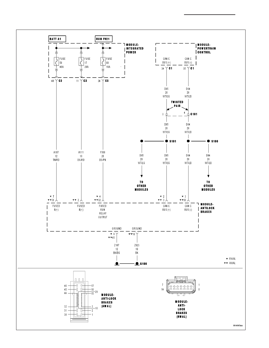
For a complete wiring diagram Refer to Section 8W.
Possible Causes
(A107) (A111) FUSED B(+) CIRCUIT OPEN OR SHORTED
(Z107) (Z923) GROUND CIRCUIT OPEN
(F500) FUSED RUN RELAY OUTPUT CIRCUIT OPEN OR SHORTED
(D65) CAN C BUS (+) CIRCUIT OPEN
(D64) CAN C BUS (-) CIRCUIT OPEN
ANTILOCK BRAKE MODULE
Diagnostic Test
1.
TEST FOR INTERMITTENT CONDITION
Turn the ignition on.
NOTE: Ensure the IOD fuse is installed and battery voltage is between 10.0 and 16.0 volts.
With the scan tool, select ECU view.
NOTE: A red X will be next to the module that is not communicating, indicating that the module is not active
on the Bus network. A green check indicates that the module is active on the Bus network.
NOTE: Check the FCM for any active CAN C hardware DTCs, perform DTC before proceeding.
Does the scan tool display a red X next to the module?
Yes
>> Go To 2
No
>> The no response condition is not present at this time. Using the wiring diagram/schematic as a guide,
inspect the wiring for chafed, pierced, pinched, and partially broken wires and the wiring harness con-
nectors for broken, bent , pushed out, and corroded terminals.
ND
ELECTRONIC CONTROL MODULES - ELECTRICAL DIAGNOSTICS
8E - 105
*NO RESPONSE FROM ABS (ANTILOCK BRAKE MODULE) (CONTINUED)
2.
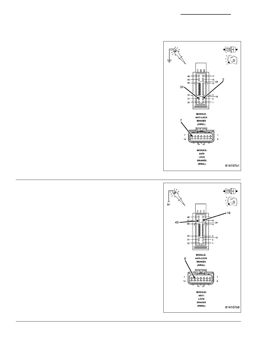
(A107) (A111) FUSED B(+) CIRCUIT OPEN OR SHORTED
Turn the ignition off.
Disconnect the Antilock Brake Module harness connector.
Using a 12-volt test light connected to ground, check each (A107) and
(A111 – not equipped on RWAL system) Fused B(+) circuit.
Does the test light illuminate brightly for each circuit?
Yes
>> Go To 3
No
>> Repair the Fused B(+) circuit for an open or short.
Perform ABS VERIFICATION TEST - VER 1.
3.
(Z107) (Z923) GROUND CIRCUIT OPEN
Using a 12-volt test light connected to 12-volts, check each (Z107) and
(Z923 – not equipped on RWAL system) ground circuit.
Does the test light illuminate brightly for each circuit?
Yes
>> Go To 4
No
>> Repair the ground circuit for an open.
Perform ABS VERIFICATION TEST - VER 1.
8E - 106
ELECTRONIC CONTROL MODULES - ELECTRICAL DIAGNOSTICS
ND
*NO RESPONSE FROM ABS (ANTILOCK BRAKE MODULE) (CONTINUED)
4.
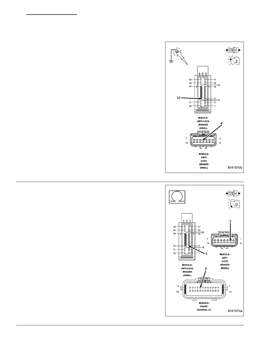
(F500) FUSED RUN RELAY OUTPUT CIRCUIT OPEN OR SHORTED
Turn the ignition on.
Using a 12-volt test light connected to ground, check the (F500) Fused
Run Relay Output circuit.
Does the test light illuminate brightly?
Yes
>> Go To 5
No
>> Repair the (F500) Fused Run Relay Output circuit for an
open or short.
Perform ABS VERIFICATION TEST - VER 1.
5.
(D65) CAN C BUS (+) CIRCUIT OPEN
Turn the ignition off.
Disconnect the FCM C1 harness connector.
Measure the resistance of the (D65) CAN C Bus (+) circuit between
the FCM connector and the Antilock Brake Module connector.
Is resistance below 5.0 ohms?
Yes
>> Go To 6
No
>> Repair the (D65) CAN C Bus (+) circuit for an open.
Perform ABS VERIFICATION TEST - VER 1.
ND
ELECTRONIC CONTROL MODULES - ELECTRICAL DIAGNOSTICS
8E - 107
Нет комментариевНе стесняйтесь поделиться с нами вашим ценным мнением.
Текст