Dodge Dakota (ND). Manual — part 933
P0720-OUTPUT SPEED SENSOR CIRCUIT (CONTINUED)
5.
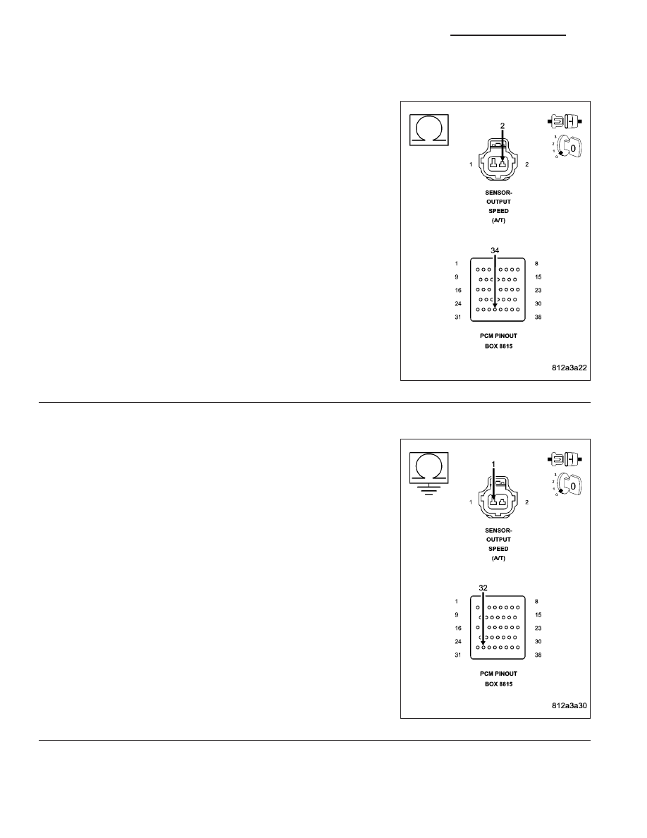
(T13) SPEED SENSOR GROUND CIRCUIT OPEN
Measure the resistance of the Speed Sensor Ground circuit from the
appropriate terminal of special tool #8815 to the Output Speed Sensor
harness connector.
Is the resistance above 5.0 ohms?
Yes
>> Repair the (T13) Speed Sensor Ground circuit for an
open.
Perform 42RLE TRANSMISSION VERIFICATION TEST -
VER 1.
No
>> Go To 6
6.
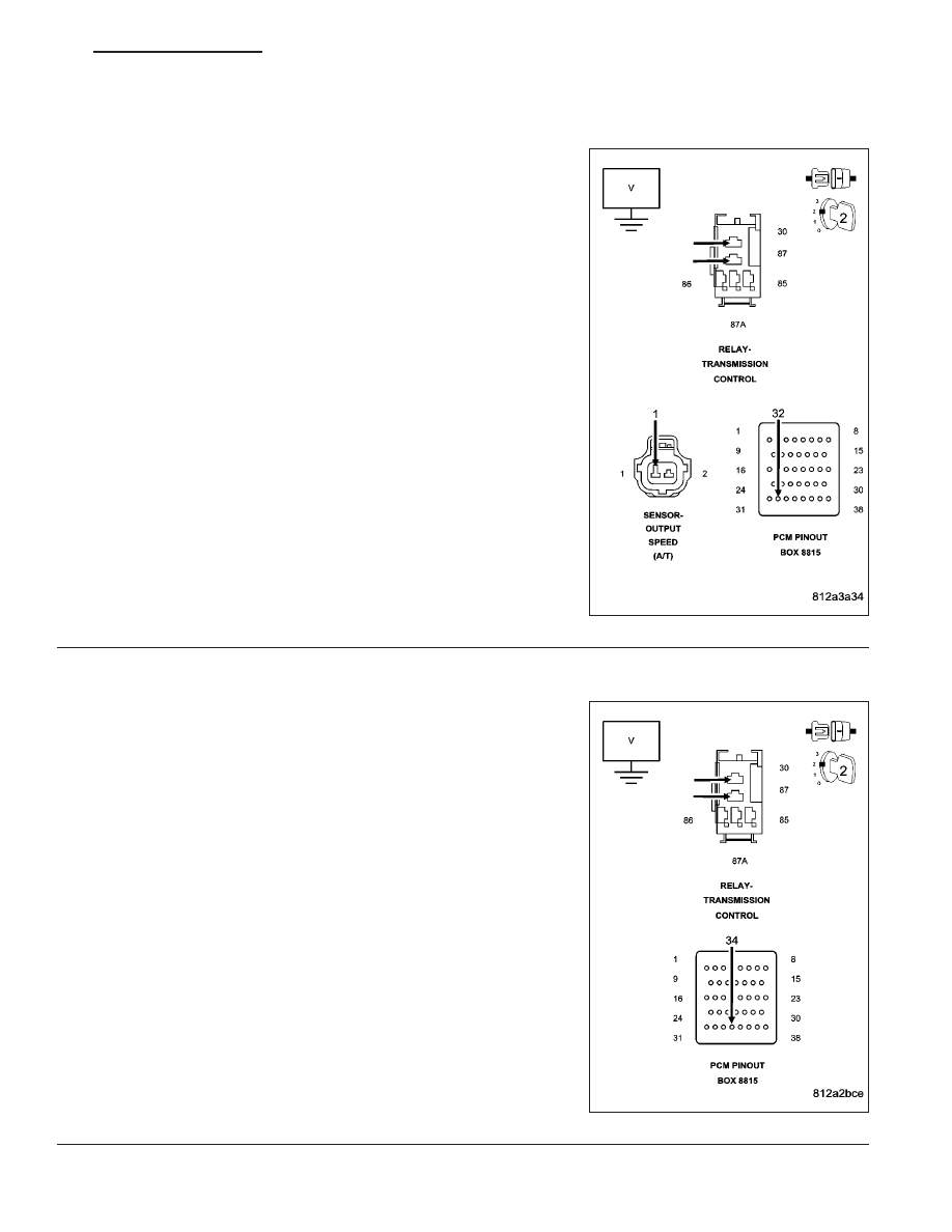
(T14) OUTPUT SPEED SENSOR SIGNAL CIRCUIT SHORT TO GROUND
Measure the resistance between ground and the (T14) Output Speed
Sensor Signal circuit.
Is the resistance below 5.0 ohms?
Yes
>> Repair the (T14) Output Speed Sensor Signal circuit for a
short to ground.
Perform 42RLE TRANSMISSION VERIFICATION TEST -
VER 1.
No
>> Go To 7
21 - 124
AUTOMATIC TRANSMISSION 42RLE - ELECTRICAL DIAGNOSTICS
ND
P0720-OUTPUT SPEED SENSOR CIRCUIT (CONTINUED)
7.
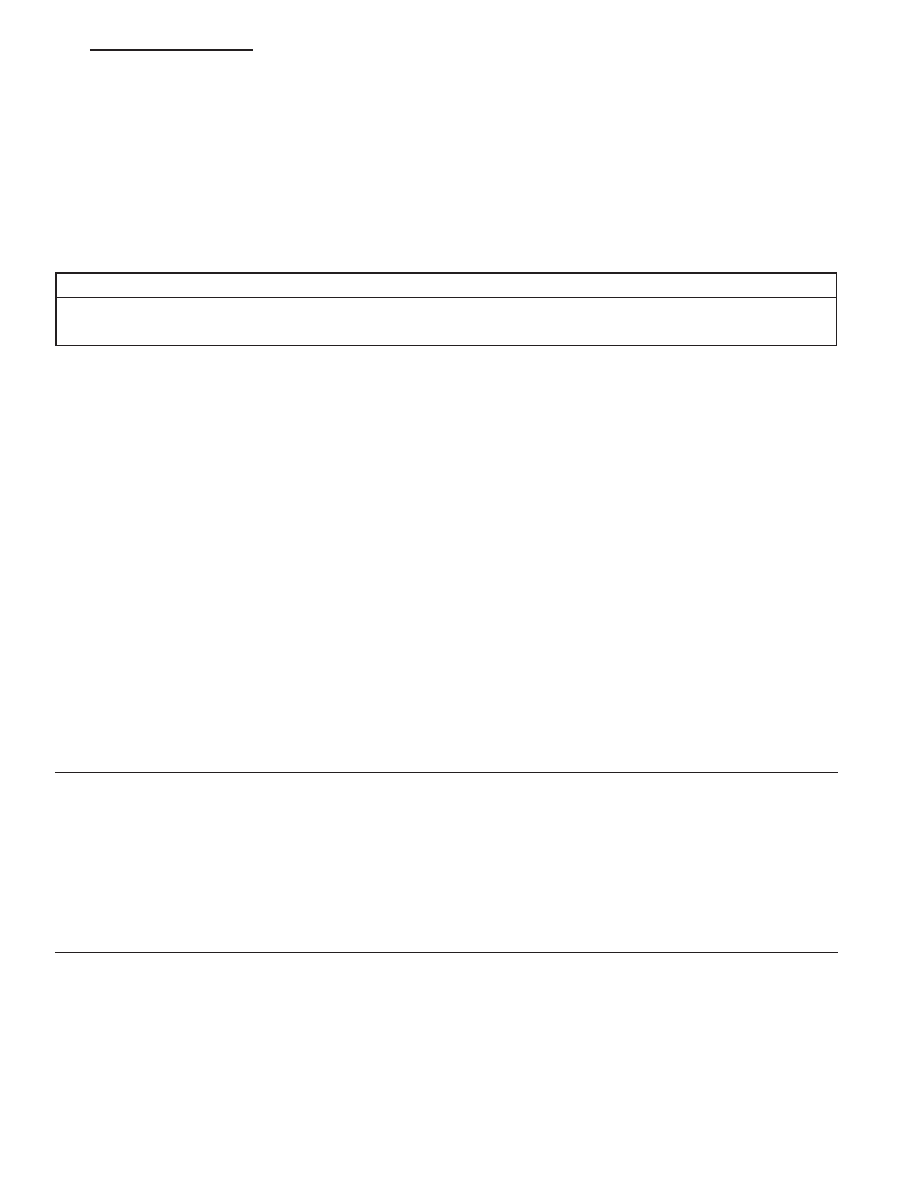
(T14) OUTPUT SPEED SENSOR SIGNAL CIRCUIT SHORT TO VOLTAGE
Remove the Transmission Control Relay.
NOTE: Check connectors - Clean/repair as necessary.
Connect a jumper wire between the (A104) Fused B+ circuit and (T16)
Transmission Control Relay Output circuit in the Transmission Control
Relay connector.
Ignition on, engine not running.
Measure the voltage of the (T14) Output Speed Sensor Signal circuit.
Is the voltage above 0.5 volt?
Yes
>> Repair the (T14) Output Speed Sensor Signal circuit for a
short to voltage.
Perform 42RLE TRANSMISSION VERIFICATION TEST -
VER 1.
No
>> Go To 8
8.
(T13) SPEED SENSOR GROUND CIRCUIT SHORT TO VOLTAGE
NOTE: The jumper wire must still be connected.
Measure the voltage of the (T13) Speed Sensor Ground circuit.
Is the voltage above 0.5 volts?
Yes
>> Repair the (T13) Speed Sensor Ground circuit for a short
to voltage.
Perform 42RLE TRANSMISSION VERIFICATION TEST -
VER 1.
No
>> Go To 9
ND
AUTOMATIC TRANSMISSION 42RLE - ELECTRICAL DIAGNOSTICS
21 - 125
P0720-OUTPUT SPEED SENSOR CIRCUIT (CONTINUED)
9.
POWERTRAIN CONTROL MODULE
Using the schematics as a guide, inspect the wiring and connectors. Repair as necessary. Pay particular attention
to all power and ground circuits.
If there are no possible causes remaining, view repair.
Repair
Replace the Powertrain Control Module per the Service Information. With the scan tool perform QUICK
LEARN.
Perform 42RLE TRANSMISSION VERIFICATION TEST - VER 1.
10.
INTERMITTENT WIRING AND CONNECTORS
The conditions necessary to set the DTC are not present at this time.
Using the schematics as a guide, inspect the wiring and connectors specific to this circuit.
Wiggle the wiring and connectors while checking for shorted and open circuits.
With the scan tool , check the EATX DTC EVENT DATA to help identify the conditions in which the DTC was set.
Were there any problems found?
Yes
>> Repair as necessary.
Perform 42RLE TRANSMISSION VERIFICATION TEST - VER 1.
No
>> Test Complete.
21 - 126
AUTOMATIC TRANSMISSION 42RLE - ELECTRICAL DIAGNOSTICS
ND
P0725-ENGINE SPEED SENSOR CIRCUIT
For the Transmission circuit diagram (Refer to 21 - TRANSMISSION/TRANSAXLE/AUTOMATIC - 42RLE - SCHE-
MATICS AND DIAGRAMS)
For a complete wiring diagram Refer to Section 8W.
•
When Monitored:
Whenever the engine is running.
•
Set Condition:
The Engine RPM is less than 390 or greater than 8000 for more than 2 seconds while the engine is running.
Possible Causes
ENGINE DTCS PRESENT
POWERTRAIN CONTROL MODULE
Always perform the Pre-Diagnostic Troubleshooting procedure before proceeding. (Refer to 21 - TRANSMIS-
SION/TRANSAXLE/AUTOMATIC - 42RLE - DIAGNOSIS AND TESTING).
Theory of Operation
The PCM uses a dual port RAM internal to the controller to send the engine speed signal to the Transmission
Control System. The calculated engine RPM is compared to a minimum and maximum value. If the PCM interprets
this signal to be out of range when the engine is running the code is set. The MIL illuminates after 10 seconds of
vehicle operation and the transmission system defaults to Limp-in mode.
Diagnostic Test
1.
CONDITION FOR DTC P0725 IS PRESENT
Start the engine.
NOTE: This DTC is not a Transmission Input Speed Sensor DTC.
With the scan tool, view DTCs.
Is the status Active for this DTC or is the STARTS SINCE SET counter set at 0?
Yes
>> Go To 2
No
>> Go To 4
2.
ENGINE DTCS PRESENT
With the scan tool, read Engine DTCs.
Are there any Engine DTC’s present?
Yes
>> Refer to Section 9 – Engine Electrical Diagnostics and perform the appropriate diagnostic procedure.
Perform 42RLE TRANSMISSION VERIFICATION TEST - VER 1.
No
>> Go To 3
ND
AUTOMATIC TRANSMISSION 42RLE - ELECTRICAL DIAGNOSTICS
21 - 127
Нет комментариевНе стесняйтесь поделиться с нами вашим ценным мнением.
Текст