Dodge Dakota (ND). Manual — part 22
RUNOUT SPECIFICATIONS
Front of Shaft
0.020 in. (0.50 mm)
Center of Shaft
0.025 in. (0.63 mm)
Rear of Shaft
0.020 in. (0.50 mm)
NOTE:
Measure front/rear runout approximately 3 inches (76 mm) from the weld seam at each end of the shaft tube for
tube lengths over 30 inches. For tube lengths under 30 inches, the maximum allowed runout is 0.020 in. (0.50
mm) for the full length of the tube.
STANDARD PROCEDURE
PROPELLER SHAFT ANGLE
NOTE: This procedure applies to the front and rear
propeller shaft.
1. Raise and support vehicle at the axles as level as
possible, allowing wheels and propeller shaft to
turn.
2. Remove universal joint snap rings if equipped, so
inclinometer base will sits flat.
3. Rotate shaft until transmission/transfer case output
yoke bearing cap is facing downward.
NOTE: Always make measurements from front to
rear and from the same side of the vehicle.
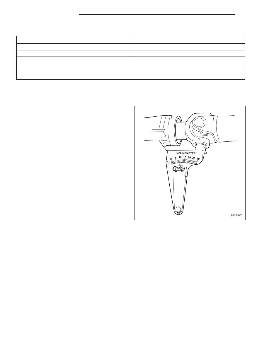
4. Place Inclinometer 7663 on yoke bearing cap or
pinion flange ring, parallel to the shaft. Center bub-
ble in sight glass and record measurement (A).
This measurement will give you the transmission
or Output Yoke Angle (A).
3 - 4
PROPELLER SHAFT
ND
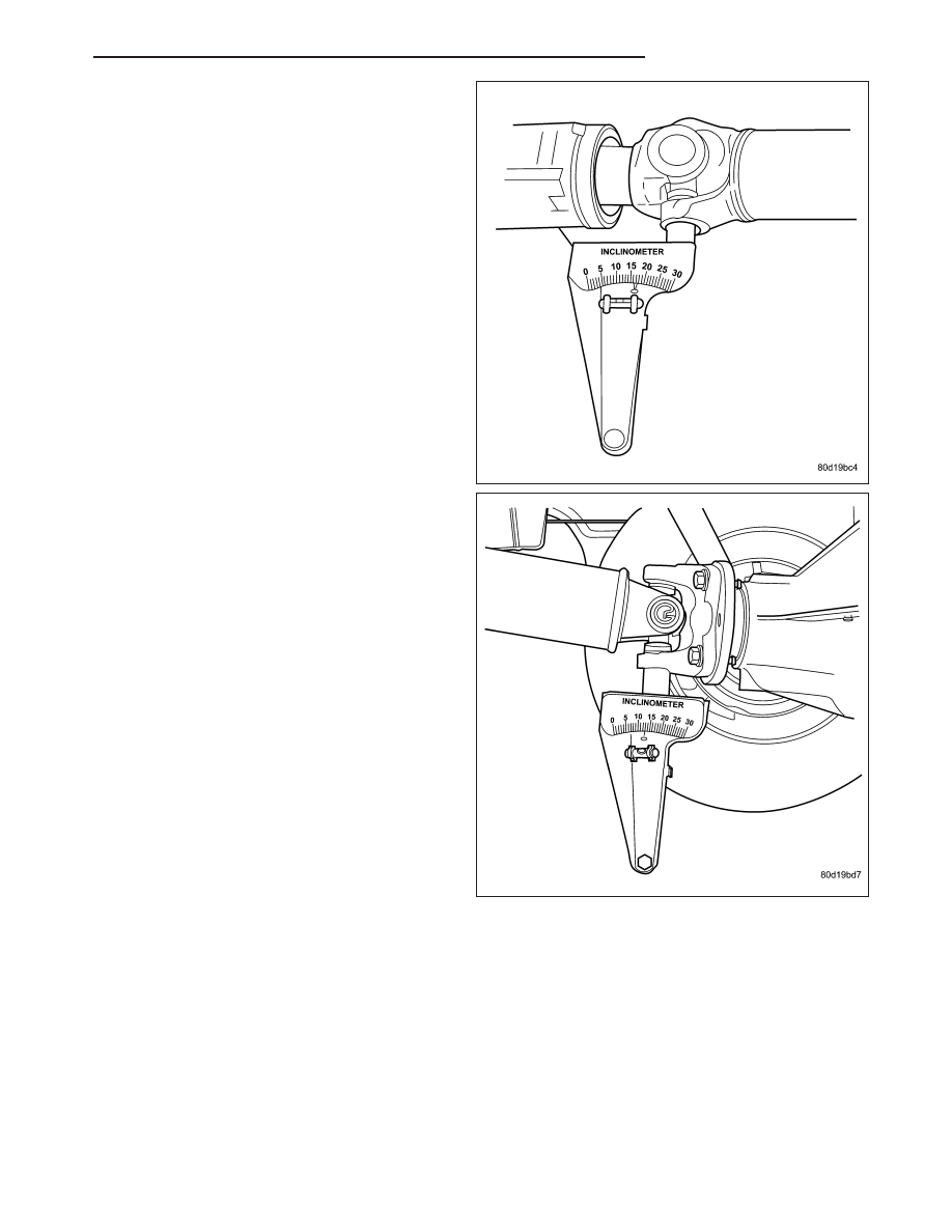
5. Rotate propeller shaft 90 degrees and place Incli-
nometer 7663 on yoke bearing cap parallel to the
shaft. Center bubble in sight glass and record mea-
surement (C). This measurement can also be taken
at the rear end of the shaft.
This measurement will give you the propeller shaft
angle (C).
6. Subtract smaller figure from larger (C minus A) to
obtain transmission output operating angle.
7. Rotate propeller shaft 90 degrees and place Incli-
nometer 7663 on pinion yoke bearing cap parallel
to the shaft. Center bubble in sight glass and
record measurement (B).
This measurement will give you the pinion shaft or
input yoke angle (B).
8. Subtract smaller figure from larger (C minus B) to
obtain axle Input Operating Angle.
PROPELLER SHAFT ANGLE RULES
•
Good cancellation of U-joint operating angles is within 1 degree.
•
Operating angles less than 3 degrees.
•
At least 1/2 of one degree continuous operating (propeller shaft) angle.
ND
PROPELLER SHAFT
3 - 5
SPECIFICATIONS
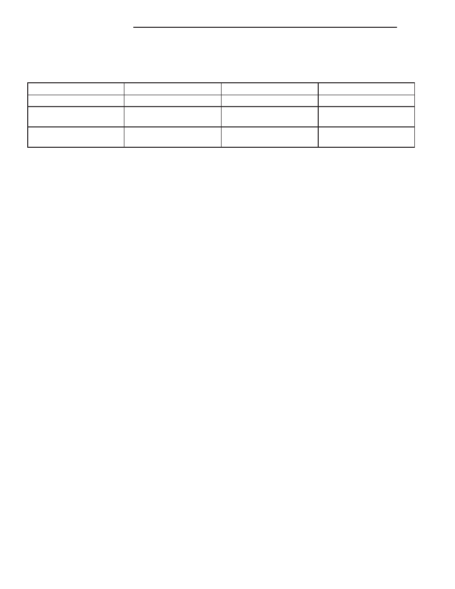
TORQUE SPECIFICATIONS
DESCRIPTION
N·m
Ft. Lbs.
In. Lbs.
Center Bearing Bolts
68
50
-
Front Companion Flange
Bolts
115
85
-
Rear Companion Flange
Bolts
115
85
-
3 - 6
PROPELLER SHAFT
ND
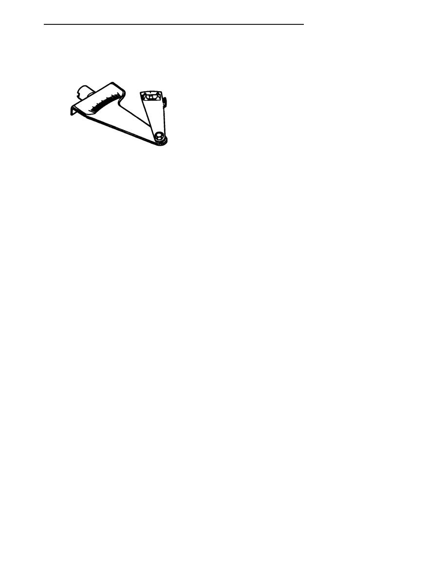
SPECIAL TOOLS
INCLINOMETER 7663
ND
PROPELLER SHAFT
3 - 7
Нет комментариевНе стесняйтесь поделиться с нами вашим ценным мнением.
Текст