Dodge Dakota (ND). Manual — part 1253
B104D–BLEND DOOR CONTROL CIRCUIT LOW (CONTINUED)
2.
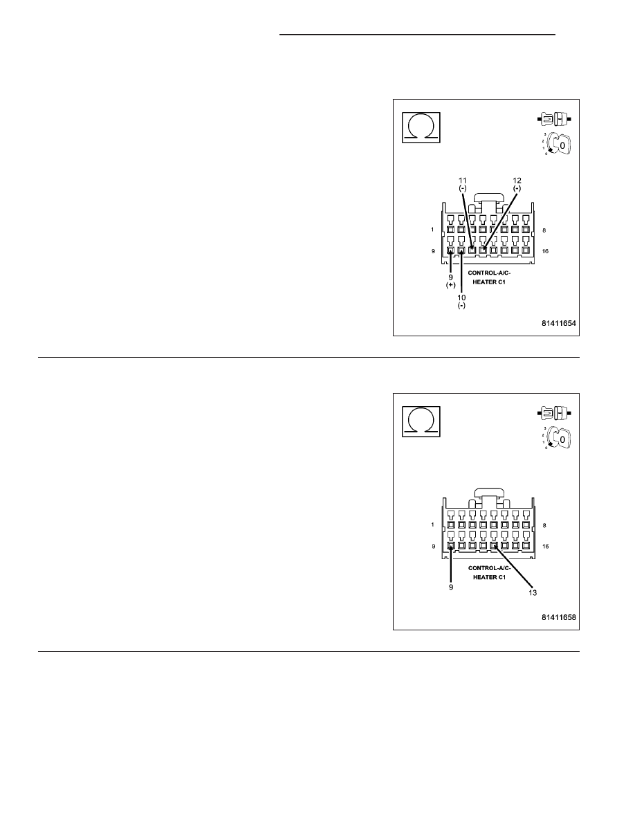
CHECK (C61) BLEND DOOR DRIVER CIRCUIT FOR A SHORT TO OTHER DOOR DRIVER CIRCUITS
Measure the resistance between the (C61) Blend Door Driver circuit
and the (C29) Mode Door 1 Driver circuit, the (C801) Mode Door 2
Driver circuit, and the (C32) Recirculation Door Driver circuit in the A/C
Heater Control C1 harness connector.
Is the resistance below 10k ohms between the (C61) Blend
Door Driver circuit and any of the other door driver circuits?
Yes
>> Repair the circuit(s) with a resistance below 10k ohms for
a short to the (C61) Blend Door Driver circuit.
Perform BODY VERIFICATION TEST - VER 1. (Refer to 8
-
ELECTRICAL/ELECTRONIC
CONTROL
MODULES/
FRONT CONTROL MODULE - DIAGNOSIS AND TEST-
ING).
No
>> Go To 3
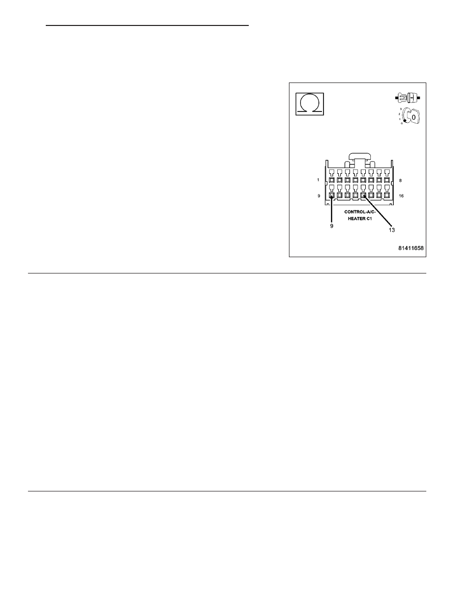
3.
CHECK BLEND DOOR ACTUATOR CIRCUIT RESISTANCE
Measure the resistance between the (C61) Blend Door Driver circuit
and the (C34) Common Door Driver circuit in the A/C Heater Control
C1 harness connector.
Is the resistance below 20 ohms?
Yes
>> Go To 4
No
>> Go To 5
24 - 10
HVAC - ELECTRICAL DIAGNOSTICS
ND
B104D–BLEND DOOR CONTROL CIRCUIT LOW (CONTINUED)
4.
CHECK (C61) BLEND DOOR DRIVER CIRCUIT FOR A SHORT TO (C34) COMMON DOOR DRIVER
CIRCUIT
Disconnect the Blend Door Actuator harness connector.
Measure the resistance between the (C61) Blend Door Driver circuit
and the (C34) Common Door Driver circuit in the A/C Heater Control
C1 harness connector.
Is the resistance below 10k ohms?
Yes
>> Repair the (C61) Blend Door Driver circuit for a short to
the (C34) Common Door Driver circuit.
Perform BODY VERIFICATION TEST - VER 1. (Refer to 8
-
ELECTRICAL/ELECTRONIC
CONTROL
MODULES/
FRONT CONTROL MODULE - DIAGNOSIS AND TEST-
ING).
No
>> Replace the Blend Door Actuator in accordance with the
Service Information.
Perform BODY VERIFICATION TEST - VER 1. (Refer to 8
-
ELECTRICAL/ELECTRONIC
CONTROL
MODULES/
FRONT
CONTROL
MODULE
-
DIAGNOSIS
AND
TESTING).
5.
RUN THE ACTUATOR DTC DETECTION TEST
Reconnect the A/C Heater Control C1 harness connector.
Turn the ignition on.
With the scan tool, erase HVAC DTCs.
With the scan tool, select System Tests and then select Actuator DTC Detection. When the test is complete, select
View DTCs.
Does the scan tool only display: B104D–BLEND DOOR CONTROL CIRCUIT LOW ?
Yes
>> Replace the A/C Heater Control in accordance with the Service Information.
Perform BODY VERIFICATION TEST - VER 1. (Refer to 8 - ELECTRICAL/ELECTRONIC CONTROL
MODULES/FRONT CONTROL MODULE - DIAGNOSIS AND TESTING).
No, Other DTC(s) Displayed
Diagnose and repair the other DTC(s). If multiple DTCs are present, beginning with the common circuit,
diagnose and repair all short high DTCs and then all short low DTCs. Refer to the Table of Contents in
this Section for a complete list of all HVAC related symptoms.
No, And No Other DTCs Displayed
Using the wiring diagram as a guide, inspect the wiring and connectors for conditions causing an inter-
mittent short. Repair as necessary.
Perform BODY VERIFICATION TEST - VER 1. (Refer to 8 - ELECTRICAL/ELECTRONIC CONTROL
MODULES/FRONT CONTROL MODULE - DIAGNOSIS AND TESTING).
ND
HVAC - ELECTRICAL DIAGNOSTICS
24 - 11
B104E–BLEND DOOR CONTROL CIRCUIT HIGH
24 - 12
HVAC - ELECTRICAL DIAGNOSTICS
ND
B104E–BLEND DOOR CONTROL CIRCUIT HIGH (CONTINUED)
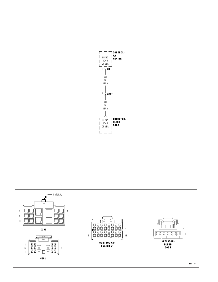
For the Manual Temperature Control (MTC) circuit diagram (Refer to 24 - HEATING & AIR CONDITIONING - SCHE-
MATICS AND DIAGRAMS).
For a complete wiring diagram Refer to Section 8W.
Theory of Operation
The A/C Heater Control drives the Blend Door Actuator via the (C61) Blend Door Driver circuit and the (C34) Com-
mon Door Driver circuit. All of the door actuators share the (C34) Common Door Driver circuit. Inside the A/C Heater
Control, each door actuator has its own unique driver, but all share a single common door driver circuit. Due to the
shared circuitry similar DTCs can set at the same time for multiple actuators depending upon the type of short, its
location, and the direction the actuator is moving when the short is present.
•
When Monitored:
When the Actuator DTC Detection Test is executed.
•
Set Condition:
If the (C61) Blend Door Driver circuit is shorted to voltage.
Possible Causes
(C61) BLEND DOOR DRIVER CIRCUIT SHORTED TO VOLTAGE
A/C HEATER CONTROL
Diagnostic Test
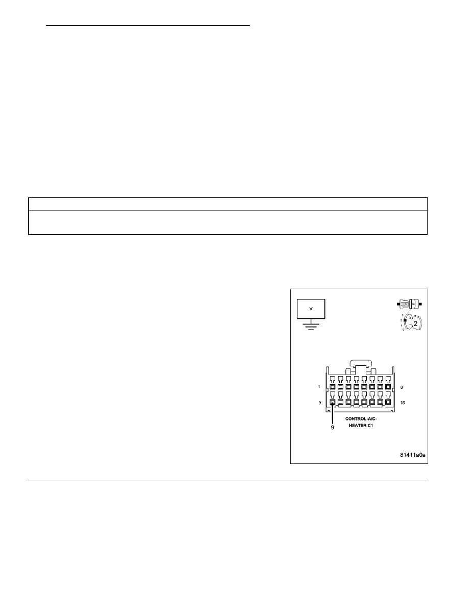
1.
CHECK (C61) BLEND DOOR DRIVER CIRCUIT FOR A SHORT TO VOLTAGE
Turn the ignition off.
Disconnect the A/C Heater Control C1 harness connector.
Turn the ignition on.
Measure the voltage of the (C61) Blend Door Driver circuit.
Is the voltage above 0.2 volts?
Yes
>> Repair the (C61) Blend Door Driver circuit for a short to
voltage.
Perform BODY VERIFICATION TEST - VER 1. (Refer to 8
-
ELECTRICAL/ELECTRONIC
CONTROL
MODULES/
FRONT CONTROL MODULE - DIAGNOSIS AND TEST-
ING).
No
>> Go To 2
ND
HVAC - ELECTRICAL DIAGNOSTICS
24 - 13
Нет комментариевНе стесняйтесь поделиться с нами вашим ценным мнением.
Текст