Dodge Dakota (ND). Manual — part 1102
ASSEMBLY
NOTE: Clean and inspect all components. Replace any components which show evidence of excessive wear
or scoring.
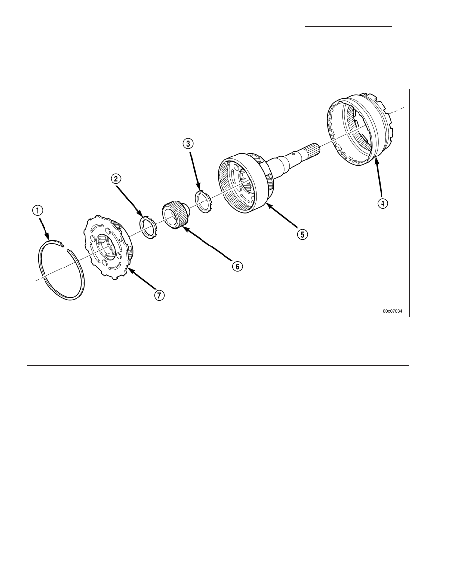
1. Install the number 11 thrust bearing (3) into the input planetary carrier (5) so that the inner race will be toward
the front of the transmission.
2. Install the input sun gear (6) into the input carrier (5).
3. Install the number 10 thrust bearing (2) onto the rear of the reverse planetary carrier (7) with the inner race
toward the carrier.
4. Install the number 9 thrust bearing onto the front of the reverse planetary carrier (7) with the outer race toward
the carrier and the inner race facing upward.
5. Install the reverse planetary gear carrier (7) into the input carrier (5).
6. Install the input annulus gear (4) into the input carrier (5).
7. Install the snap-ring (1) to hold the input annulus gear (4) into the input carrier (5).
MECHANISM-SHIFT
DESCRIPTION
The gear shift mechanism provides six shift positions which are:
•
Park (P)
•
Reverse (R)
Reverse/Input Planetary Carrier Assembly
1 - SNAP-RING
5 - INPUT PLANETARY CARRIER
2 - THRUST BEARING NUMBER 10
6 - INPUT SUN GEAR
3 - THRUST BEARING NUMBER 11
7 - REVERSE PLANETARY CARRIER
4 - INPUT ANNULUS
21 - 800
AUTOMATIC TRANSMISSION 545RFE - SERVICE INFORMATION
ND
•
Neutral (N)
•
Drive (D)
•
Manual second (2)
•
Manual low (1)
OPERATION
MANUAL LOW (1) range provides FIRST gear only. Overrun braking is also provided in this range. MANUAL SEC-
OND (2) range provides FIRST and SECOND gear only.
DRIVE range provides FIRST, SECOND, THIRD and OVERDRIVE FOURTH and FIFTH gear ranges. The shift into
OVERDRIVE FOURTH and FIFTH gear range occurs only after the transmission has completed the shift into D
THIRD gear range. No further movement of the shift mechanism is required to complete the 3-4 or 4-5 shifts.
The FOURTH and FIFTH gear upshifts occurs automatically when the overdrive selector switch is in the ON posi-
tion. An upshift to FOURTH and FIFTH gears may not occur or may be delayed in some of the possible shift sched-
ules. (Refer to 8 - ELECTRICAL/ELECTRONIC CONTROL MODULES/TRANSMISSION CONTROL MODULE -
OPERATION)
SWITCH VALVE-SOLENOID
DESCRIPTION
The Solenoid Switch Valve (SSV) is located in the valve body and controls the direction of the transmission fluid
when the L/R-TCC solenoid is energized.
OPERATION
The Solenoid Switch Valve controls line pressure from the LR-TCC solenoid. In 1st gear, the SSV will be in the
downshifted position, thus directing fluid to the L/R clutch circuit. In 2nd, 3rd, 4th, and 5th gears, the solenoid switch
valve will be in the upshifted position and directs the fluid into the torque converter clutch (TCC) circuit.
When shifting into 1st gear, a special hydraulic sequence is performed to ensure SSV movement into the down-
shifted position. The L/R pressure switch is monitored to confirm SSV movement. If the movement is not confirmed
(the L/R pressure switch does not close), 2nd gear is substituted for 1st. A DTC will be set after three unsuccessful
attempts are made to get into 1st gear in one given key start.
CONVERTER-TORQUE
DESCRIPTION
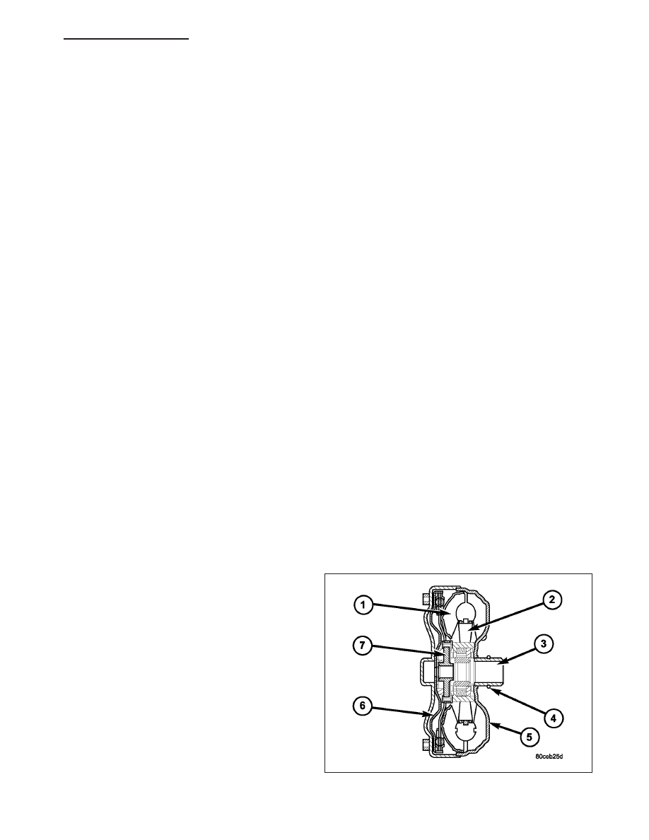
The torque converter is a hydraulic device that cou-
ples the engine crankshaft to the transmission. The
torque converter consists of an outer shell with an
internal turbine (1), a stator (2), an overrunning clutch,
an impeller (5), and an electronically applied converter
clutch (6). The converter clutch provides reduced
engine
speed
and
greater
fuel
economy
when
engaged. Clutch engagement also provides reduced
transmission fluid temperatures. The torque converter
hub (3) drives the transmission oil (fluid) pump and
contains an o-ring seal (4) to better control oil flow.
The torque converter is a sealed, welded unit that is
not repairable and is serviced as an assembly.
CAUTION: The torque converter must be replaced
if a transmission failure resulted in large amounts
of metal or fiber contamination in the fluid.
ND
AUTOMATIC TRANSMISSION 545RFE - SERVICE INFORMATION
21 - 801
IMPELLER
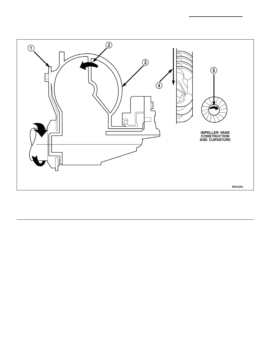
The impeller is an integral part of the converter housing. The impeller consists of curved blades placed radially
along the inside of the housing on the transmission side of the converter. As the converter housing is rotated by the
engine, so is the impeller, because they are one and the same and are the driving members of the system.
Impeller
1 - ENGINE FLEXPLATE
4 - ENGINE ROTATION
2 - OIL FLOW FROM IMPELLER SECTION INTO TURBINE
SECTION
5 - ENGINE ROTATION
3 - IMPELLER VANES AND COVER ARE INTEGRAL
21 - 802
AUTOMATIC TRANSMISSION 545RFE - SERVICE INFORMATION
ND
TURBINE
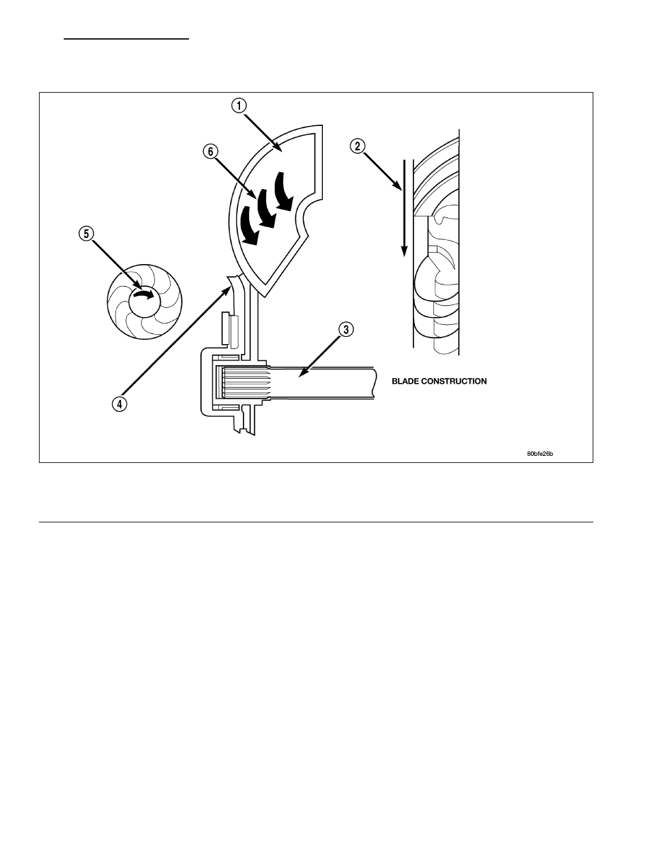
The turbine is the output, or driven, member of the converter. The turbine is mounted within the housing opposite
the impeller, but is not attached to the housing. The input shaft is inserted through the center of the impeller and
splined into the turbine. The design of the turbine is similar to the impeller, except the blades of the turbine are
curved in the opposite direction.
Turbine
1 - TURBINE VANE
4 - PORTION OF TORQUE CONVERTER COVER
2 - ENGINE ROTATION
5 - ENGINE ROTATION
3 - INPUT SHAFT
6 - OIL FLOW WITHIN TURBINE SECTION
ND
AUTOMATIC TRANSMISSION 545RFE - SERVICE INFORMATION
21 - 803
Нет комментариевНе стесняйтесь поделиться с нами вашим ценным мнением.
Текст