Dodge Dakota (ND). Manual — part 236
OPEN-CIRCUIT VOLTAGE TEST
A battery open-circuit voltage (no load) test will show
the approximate state-of-charge of a battery. This test
can be used in place of the hydrometer test when a
hydrometer is not available, or for maintenance-free
batteries with non-removable cell caps.
Before proceeding with this test, completely charge
the battery (Refer to 8 - ELECTRICAL/BATTERY SYS-
TEM/BATTERY - STANDARD PROCEDURE - BAT-
TERY CHARGING).
1. Before measuring the open-circuit voltage, the sur-
face charge must be removed from the battery.
Turn on the headlamps for fifteen seconds, then
allow up to five minutes for the battery voltage to
stabilize.
2. Disconnect and isolate both battery cables, nega-
tive cable first.
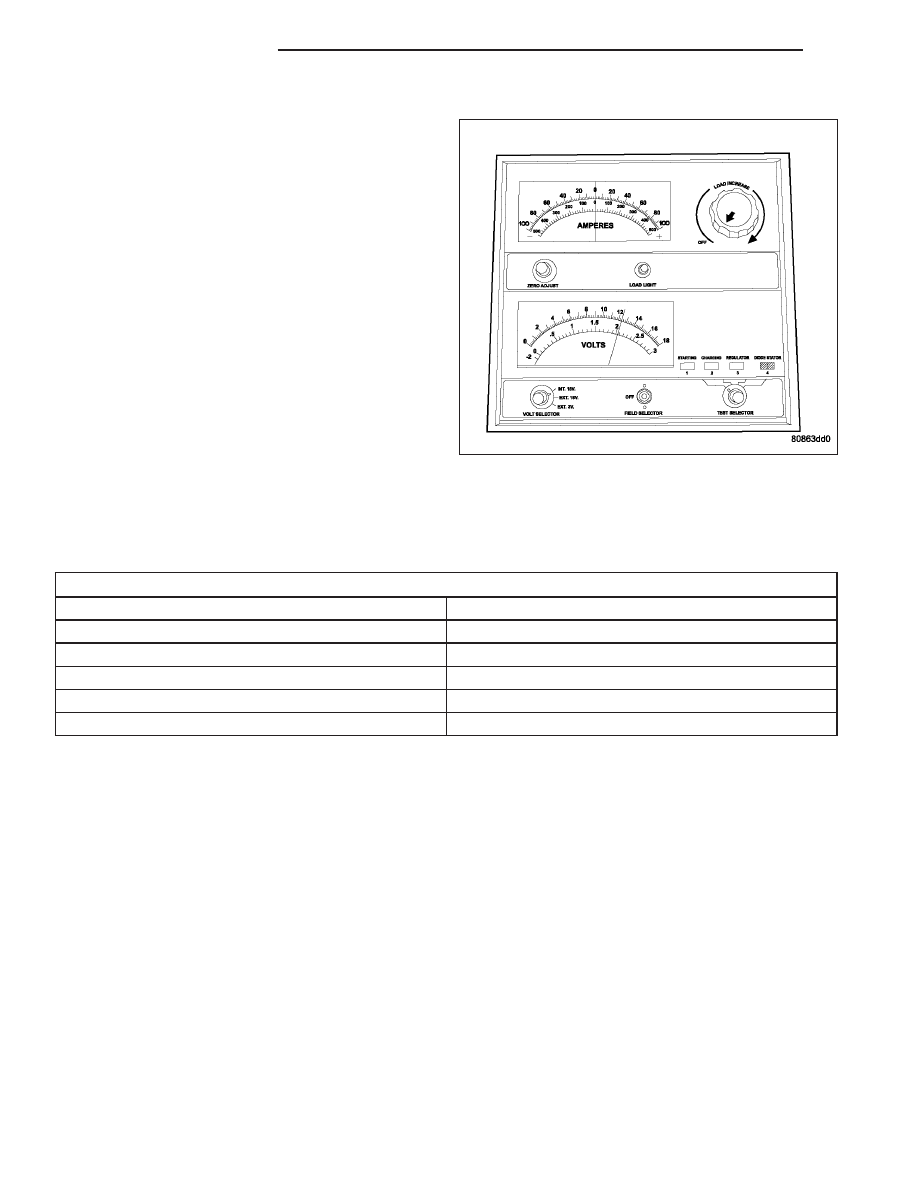
3. Using a voltmeter connected to the battery posts
(see the instructions provided by the manufacturer
of the voltmeter), measure the open-circuit voltage.
See the Open-Circuit Voltage Table. This voltage reading will indicate the battery state-of-charge, but will not reveal
its cranking capacity. If a battery has an open-circuit voltage reading of 12.4 volts or greater, it may be load tested
to reveal its cranking capacity (Refer to 8 - ELECTRICAL/BATTERY SYSTEM/BATTERY - STANDARD PROCE-
DURE - USING MICRO 420 BATTERY TESTER).
OPEN CIRCUIT VOLTAGE TABLE
Open Circuit Voltage
Charge Percentage
11.7 volts or less
0%
12.0 volts
25%
12.3 volts
50%
12.6 volts
75%
12.8 volts or more
100%
8F - 14
BATTERY SYSTEM
ND
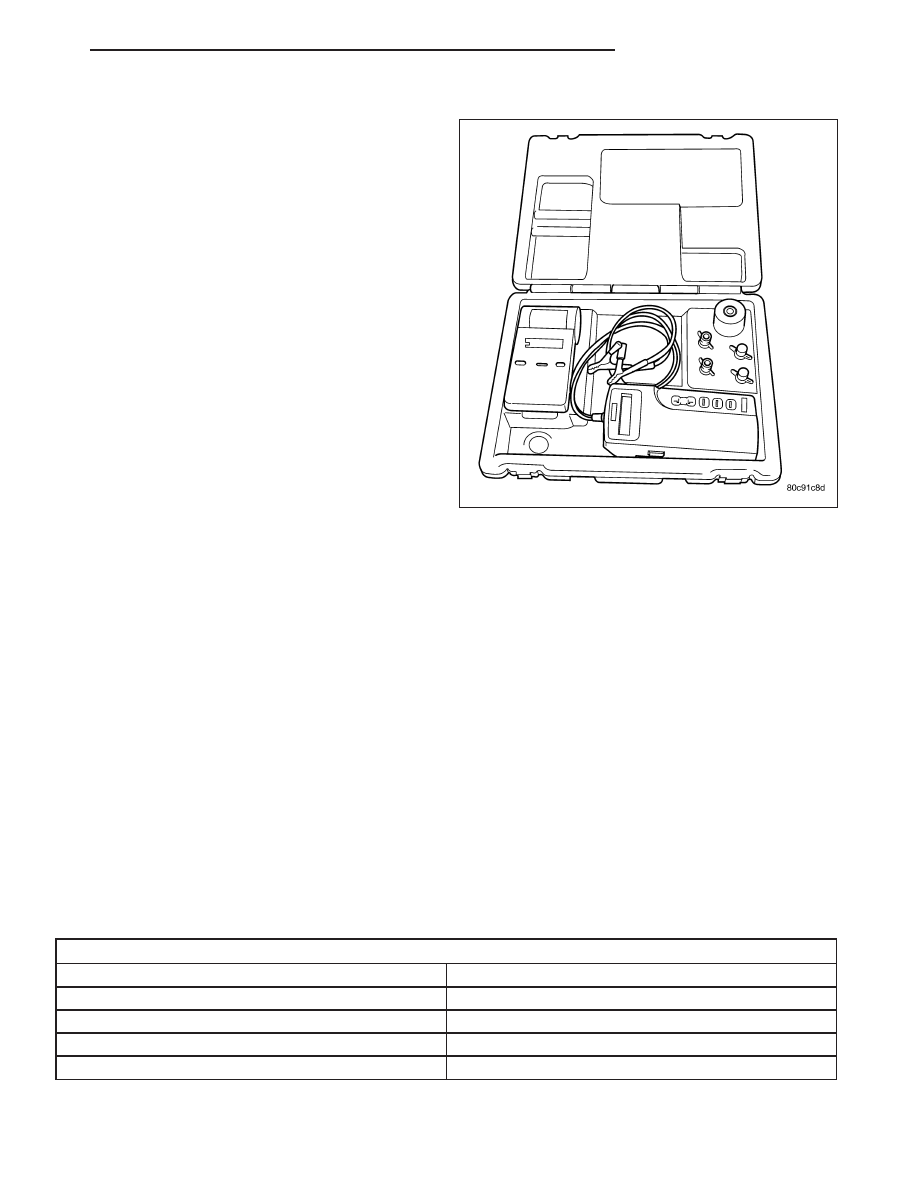
MICRO 420 BATTERY TESTER
Always use the Micro 420 Instruction Manual that was
supplied with the tester as a reference. If the Instruc-
tion Manual is not available the following procedure
can be used:
WARNING: ALWAYS WEAR APPROPRIATE EYE
PROTECTION
AND
USE
EXTREME
CAUTION
WHEN WORKING WITH BATTERIES.
BATTERY TESTING
1. If testing the battery OUT-OF-VEHICLE, clean the
battery terminals with a wire brush before testing,
(Refer to 8 - ELECTRICAL/BATTERY SYSTEM -
CLEANING). If the battery is equipped with side
post terminals, install and tighten the supplied lead
terminal stud adapters. Do not use steel bolts. Fail-
ure to properly install the stud adapters, or using
stud adapters that are dirty or worn-out may result
in false test readings.
2. If testing the battery IN-THE-VEHICLE, make cer-
tain all of the vehicle accessory loads are OFF,
including the ignition. The preferred test position
is at the battery terminal. If the battery is not accessible, you may test using both the positive and negative
jumper posts. Select TESTING AT JUMPER POST when connecting to that location.
3. Connect the tester to the battery or jumper posts, the red clamp to positive (+) and the black clamp to negative
(–).
NOTE: Multiple batteries connected in parallel must have the ground cable disconnected to perform a bat-
tery test. Failure to disconnect may result in false battery test readings.
4. Using the ARROW key select in or out of vehicle testing and press ENTER to make a selection.
5. If not selected, choose the Cold Cranking Amp (CCA) battery rating. Or select the appropriate battery rating for
your area (see menu). The tester will then run its self programmed test of the battery and display the results.
Refer to the test result table noted below.
CAUTION: If REPLACE BATTERY is the result of the test, this may mean a poor connection between the
vehicle’s cables and battery exists. After disconnecting the vehicle’s battery cables from the battery, retest
the battery using the OUT-OF-VEHICLE test before replacing.
6. While viewing the battery test result, press the CODE button and the tester will prompt you for the last 4 digits
of the VIN. Use the UP/DOWN arrow buttons to scroll to the correct character; then press ENTER to select and
move to the next digit. Then press the ENTER button to view the SERVICE CODE. Pressing the CODE button
a second time will return you to the test results.
BATTERY TEST RESULTS
GOOD BATTERY
Return to service
GOOD - RECHARGE
Fully charge battery and return to service
CHARGE & RETEST
Fully charge battery and retest battery
REPLACE BATTERY
Replace the battery and retest complete system
BAD-CELL REPLACE
Replace the battery and retest complete system
ND
BATTERY SYSTEM
8F - 15

NOTE: The SERVICE CODE is required on every warranty claim submitted for battery replacement.
REMOVAL
NOTE: It may be necessary to use a battery termi-
nal puller (2) if the battery cable terminal clamps
are seized on to the battery posts.
1. Turn the ignition switch to the Off position. Be cer-
tain that all electrical accessories are turned off.
2. Loosen the battery negative cable terminal (4)
clamp pinch-bolt hex nut.
3. Disconnect the battery negative cable terminal
clamp from the battery negative terminal post. If
necessary, use a battery terminal puller to remove
the terminal clamp from the battery post.
4. Loosen the battery positive cable terminal (2)
clamp pinch-bolt hex nut.
5. Disconnect the battery positive cable terminal
clamp from the battery positive terminal post. If
necessary, use a battery terminal puller to remove
the terminal clamp from the battery post.
8F - 16
BATTERY SYSTEM
ND
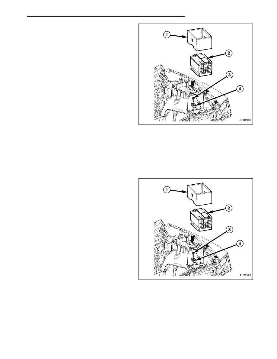
6. Remove the battery thermal guard (1).
7. Remove the battery hold down (4) and bolt (3) from
the battery (2).
WARNING: WEAR A SUITABLE PAIR OF RUBBER GLOVES WHEN REMOVING A BATTERY BY HAND.
SAFETY GLASSES SHOULD ALSO BE WORN. IF THE BATTERY IS CRACKED OR LEAKING, THE ELECTRO-
LYTE CAN BURN THE SKIN AND EYES.
8. Remove the battery (2) from the vehicle.
INSTALLATION
1. Clean and inspect the battery case, terminal posts
and battery cable clamps, (Refer to 8 - ELECTRI-
CAL/BATTERY SYSTEM - CLEANING).
2. Position the battery (2) into the vehicle. Ensure that
the battery positive and negative terminal posts are
correctly positioned. The battery cable terminal
clamps must reach the correct battery terminal post
without stretching the cables.
3. Install the thermal guard (1) and slide battery
toward fender.
4. Install the battery hold down (4) and bolt (3) onto
the battery.
ND
BATTERY SYSTEM
8F - 17
Нет комментариевНе стесняйтесь поделиться с нами вашим ценным мнением.
Текст