Dodge Dakota (ND). Manual — part 401
B1B7A-PASSENGER SEAT WEIGHT SENSOR 3 - LEFT FRONT INPUT CIRCUIT HIGH (CONTINUED)
6.
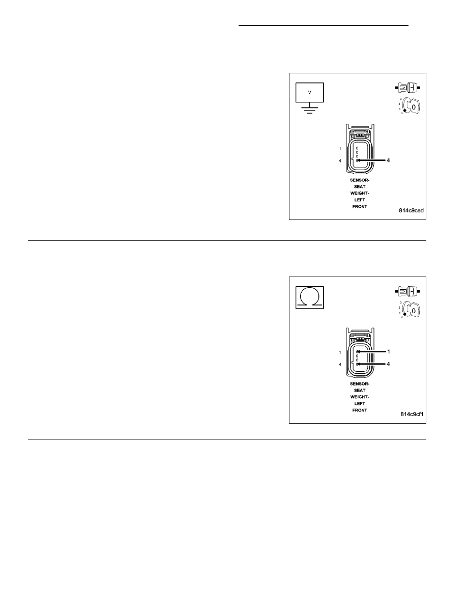
CHECK (R717) LT-FT SEAT WEIGHT SENSOR SIGNAL CIRCUIT FOR A SHORT TO VOLTAGE
WARNING: To avoid personal injury or death, turn the ignition off,
disconnect the battery and wait two minutes before proceeding.
Disconnect the OCM C2 connector.
Disconnect the Left-Front Seat Weight Sensor connector.
Measure the voltage of the (R717) LT-FT Seat Weight Sensor Signal
circuit.
Is the voltage above 0.2 volts?
Yes
>>
NOTE: Do not attempt to repair the Seat Harness. Replace the
Seat Harness if the condition inspecting or testing for is present
in the Seat Harness.
Replace the Passenger Seat Harness in accordance with
the Service Information.
Perform OCS VERIFICATION TEST - VER 1.
No
>> Go To 7
7.
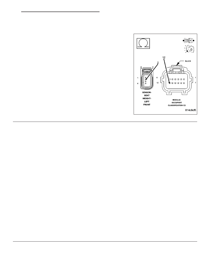
CHECK (R717) LT-FT SEAT WEIGHT SENSOR SIGNAL CIRCUIT FOR A SHORT TO (R701) SEAT WEIGHT
SENSOR 5 VOLT CIRCUIT
Measure the resistance between the (R717) LT-FT Seat Weight Sen-
sor Signal circuit and the (R701) Seat Weight Sensor 5 Volt circuit.
Is the resistance below 10K ohms?
Yes
>>
NOTE: Do not attempt to repair the Seat Harness. Replace the
Seat Harness if the condition inspecting or testing for is present
in the Seat Harness.
Replace the Passenger Seat Harness in accordance with
the Service Information.
Perform OCS VERIFICATION TEST - VER 1.
No
>> Go To 8
8O - 200
RESTRAINTS - ELECTRICAL DIAGNOSTICS
ND
B1B7A-PASSENGER SEAT WEIGHT SENSOR 3 - LEFT FRONT INPUT CIRCUIT HIGH (CONTINUED)
8.
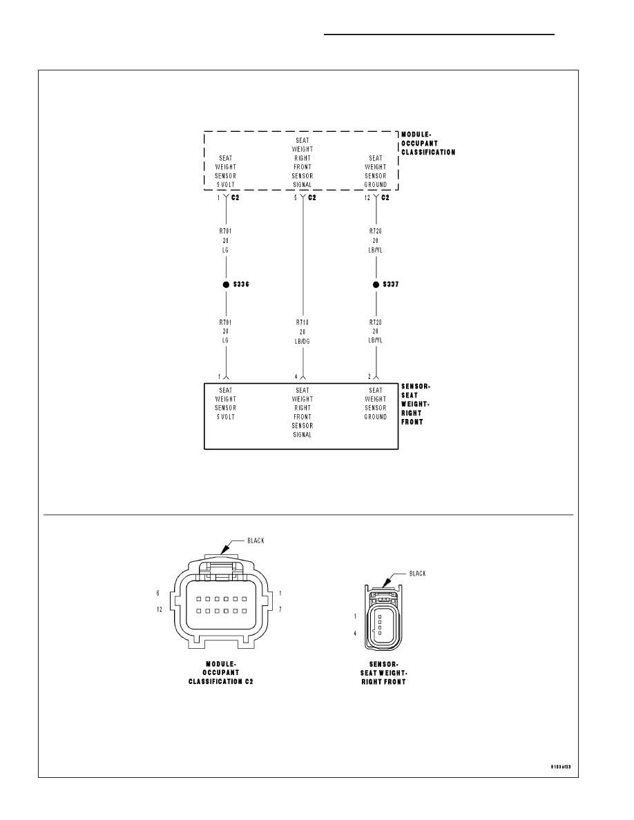
CHECK (R728) SEAT WEIGHT SENSOR GROUND CIRCUIT FOR AN OPEN
Measure the resistance of the (R728) Seat Weight Sensor Ground cir-
cuit between the OCM C2 connector and the Left-Front Seat Weight
Sensor connector.
Is the resistance below 5.0 ohms?
Yes
>> Replace the OCM in accordance with the Service Informa-
tion.
Perform OCS VERIFICATION TEST - VER 1.
No
>>
NOTE: Do not attempt to repair the Seat Harness. Replace the
Seat Harness if the condition inspecting or testing for is present
in the Seat Harness.
Replace the Passenger Seat Harness in accordance with
the Service Information.
Perform OCS VERIFICATION TEST - VER 1.
9.
TEST FOR INTERMITTENT CONDITION
With the scan tool, record and erase all DTCs from all Airbag modules.
If any ACTIVE codes are present they must be resolved before diagnosing any stored codes.
WARNING: To avoid personal injury or death, turn the ignition off, disconnect the battery and wait two min-
utes before proceeding.
Using the wiring diagram/schematic as a guide, inspect the wiring and connectors.
Look for chaffed, pierced, pinched, or partially broken wires and broken, bent, pushed out, spread, corroded, or
contaminated terminals.
The following additional checks may assist you in identifying a possible intermittent problem.
Reconnect any disconnected components and harness connector.
WARNING: To avoid personal injury or death, turn the ignition on, then reconnect the battery.
With the scan tool, monitor active codes as you work through the following steps.
WARNING: To avoid personal injury or death, maintain a safe distance from all airbags while performing the
following steps.
Wiggle the wiring harness and connectors of the related airbag circuit or component.
If codes are related to the Driver Airbag circuits, rotate the steering wheel from stop to stop.
If only stored codes return, continue the test until the problem area has been isolated.
In the previous steps you have attempted to recreate the conditions responsible for setting the active DTC in ques-
tion.
Does the scan tool display any ACTIVE DTCs?
Yes
>> Select appropriate symptom from Symptom List.
No
>> No problem found at this time. Erase all codes before returning vehicle to customer.
ND
RESTRAINTS - ELECTRICAL DIAGNOSTICS
8O - 201
B1B7D-PASSENGER SEAT WEIGHT SENSOR 2 - RIGHT FRONT PERFORMANCE
8O - 202
RESTRAINTS - ELECTRICAL DIAGNOSTICS
ND

B1B7D-PASSENGER SEAT WEIGHT SENSOR 2 - RIGHT FRONT PERFORMANCE (CONTINUED)
For the Occupant Classification System circuit diagram (Refer to 8 - ELECTRICAL/RESTRAINTS - SCHEMATICS
AND DIAGRAMS).
For a complete wiring diagram Refer to Section 8W.
•
When Monitored:
When CAN ignitions status is Run or SNA, during auto zero and while performing the Occupant Classification
Module System Verification Test.
•
Set Condition:
During the occupant classification verification test: if the module detects that the sensor input is less than 1.4
volts or greater than 3.6 volts. During auto zero: if the module detects that the sensor input is less than 1 volt
or greater than 4 volts.
Possible Causes
PASSENGER SEAT HARNESS WIRES CHAFFED, PIERCED, PINCHED, PARTIALLY BROKEN
PASSENGER SEAT HARNESS CONNECTOR TERMINALS BROKEN, BENT PUSHED OUT, SPREAD,
CORRODED, CONTAMINATED
RIGHT-FRONT PASSENGER SEAT WEIGHT SENSOR
DAMAGE TO THE PASSENGER SEAT STRUCTURE, RISER ASSEMBLY, CROSSMEMBERS, SEAT TRACKS,
FLOOR PAN
OCCUPANT CLASSIFICATION MODULE (OCM)
Diagnostic Test
1.
CHECK FOR ACTIVE INTERNAL FAULTS, IGNITION FAULTS, & BATTERY FAULTS IN THE OCCUPANT
CLASSIFICATION MODULE (OCM)
NOTE: Ensure the battery is fully charged.
NOTE: When reconnecting Airbag system components, the ignition must be turned off and the battery must
be disconnected.
Turn the ignition on, then off, and then on again.
With the scan tool, read Occupant Classification Module (OCM) DTCs.
Does the scan tool display any active DTCs relating to internal faults, ignition faults, or battery faults?
Yes
>> Diagnose and repair the DTCs. Refer to the Table of Contents in this Section for a complete list of
symptoms.
No
>> Go To 2
2.
VERIFY THAT DTC B1B7D–PASSENGER SEAT WEIGHT SENSOR 2 - RIGHT FRONT PERFORMANCE IS
ACTIVE
With the scan tool, read OCM DTCs.
Does the scan tool display active: B1B7D–PASSENGER SEAT WEIGHT SENSOR 2 - RIGHT FRONT PER-
FORMANCE?
Yes
>> Go To 3
No
>> Go To 5
ND
RESTRAINTS - ELECTRICAL DIAGNOSTICS
8O - 203
Нет комментариевНе стесняйтесь поделиться с нами вашим ценным мнением.
Текст