Dodge Dakota (ND). Manual — part 448
U0184-LOST COMMUNICATION WITH RADIO
For a complete wiring diagram Refer to Section 8W.
(Refer to 8 - ELECTRICAL/ELECTRONIC CONTROL MODULES - DIAGNOSIS AND TESTING) for the diagnostic
test procedure.
U0186-LOST COMMUNICATION WITH AUDIO AMPLIFIER
For a complete wiring diagram Refer to Section 8W.
(Refer to 8 - ELECTRICAL/ELECTRONIC CONTROL MODULES - DIAGNOSIS AND TESTING) for the diagnostic
test procedure.
U0195-LOST COMMUNICATION WITH SDARS
For a complete wiring diagram Refer to Section 8W.
(Refer to 8 - ELECTRICAL/ELECTRONIC CONTROL MODULES - DIAGNOSIS AND TESTING) for the diagnostic
test procedure.
U0196-LOST COMMUNICATION WITH VEHICLE ENTERTAINMENT CONTROL
MODULE
For a complete wiring diagram Refer to Section 8W.
(Refer to 8 - ELECTRICAL/ELECTRONIC CONTROL MODULES - DIAGNOSIS AND TESTING) for the diagnostic
test procedure.
U0197-LOST COMMUNICATION WITH HANDS FREE PHONE MODULE
For a complete wiring diagram Refer to Section 8W.
(Refer to 8 - ELECTRICAL/ELECTRONIC CONTROL MODULES - DIAGNOSIS AND TESTING) for the diagnostic
test procedure.
U0199-LOST COMMUNICATION WITH DRIVER DOOR MODULE
For a complete wiring diagram Refer to Section 8W.
(Refer to 8 - ELECTRICAL/ELECTRONIC CONTROL MODULES - DIAGNOSIS AND TESTING) for the diagnostic
test procedure.
U0200-LOST COMMUNICATION WITH PASSENGER DOOR MODULE
For a complete wiring diagram Refer to Section 8W.
(Refer to 8 - ELECTRICAL/ELECTRONIC CONTROL MODULES - DIAGNOSIS AND TESTING) for the diagnostic
test procedure.
U0208-LOST COMMUNICATION WITH HEATED SEAT CONTROL MODULE
For a complete wiring diagram Refer to Section 8W.
(Refer to 8 - ELECTRICAL/ELECTRONIC CONTROL MODULES - DIAGNOSIS AND TESTING) for the diagnostic
test procedure.
U0209-LOST COMMUNICATION WITH MEMORY SEAT CONTROL MODULE
For a complete wiring diagram Refer to Section 8W.
(Refer to 8 - ELECTRICAL/ELECTRONIC CONTROL MODULES - DIAGNOSIS AND TESTING) for the diagnostic
test procedure.
8O - 388
RESTRAINTS - ELECTRICAL DIAGNOSTICS
ND

U1414-IMPLAUSIBLE/MISSING ECU CONFIGURATION DATA
For a complete wiring diagram Refer to Section 8W.
(Refer to 8 - ELECTRICAL/ELECTRONIC CONTROL MODULES - DIAGNOSIS AND TESTING) for the diagnostic
test procedure.
For a complete wiring diagram Refer to Section 8W.
•
When Monitored:
With the ignition on. The ORC on board diagnostics continuously monitors the CAN Bus message from the
FCM containing the ORC Configuration Data.
•
Set Condition:
This DTC will set if the appropriate CAN Bus message is not received by the ORC.
Possible Causes
FRONT CONTROL MODULE
Diagnostic Test
1.
FRONT CONTROL MODULE FAILURE
Turn the ignition on.
With the scan tool, read FCM DTCs.
Does the scan tool display any Front Control Module DTCs?
Yes
>> Select appropriate symptom from Symptom List. Repair all FCM active DTCs and before diagnosing the
ORC DTCs.
No
>> Replace the Front Control Module in accordance with the Service Information.
Perform the ORC VERIFICATION TEST-VER. 1
ND
RESTRAINTS - ELECTRICAL DIAGNOSTICS
8O - 389
U1415-IMPLAUSIBLE/MISSING VEHICLE CONFIGURATION DATA
For a complete wiring diagram Refer to Section 8W.
(Refer to 8 - ELECTRICAL/ELECTRONIC CONTROL MODULES - DIAGNOSIS AND TESTING) for the diagnostic
test procedure.
For a complete wiring diagram Refer to Section 8W.
•
When Monitored:
With the ignition on. The ORC on board diagnostics loads the ORC Configuration Data from the FCM CAN
Bus message.
•
Set Condition:
This DTC will set if the CAN Bus message was received but the information is invalid or corrupt.
Possible Causes
OCCUPANT RESTRAINT CONTROLLER (ORC)
Diagnostic Test
1.
OCCUPANT RESTRAINT CONTROLLER
WARNING: To avoid personal injury or death, turn the ignition off, disconnect the battery and wait two min-
utes before proceeding.
WARNING: If the Occupant Restraint Controller is dropped at any time, it must be replaced. Failure to take
the proper precautions can result in accidental airbag deployment and personal injury or death.
Disconnect the ORC harness connector(s).
NOTE: Check connectors - Clean and repair as necessary.
NOTE: When reconnecting airbag system components the Ignition must be turned off and the Battery must
be disconnected.
Repair
Replace the Occupant Restraint Controller in accordance with Service Information.Perform the ORC
VERIFICATION TEST-VER. 1
8O - 390
RESTRAINTS - ELECTRICAL DIAGNOSTICS
ND
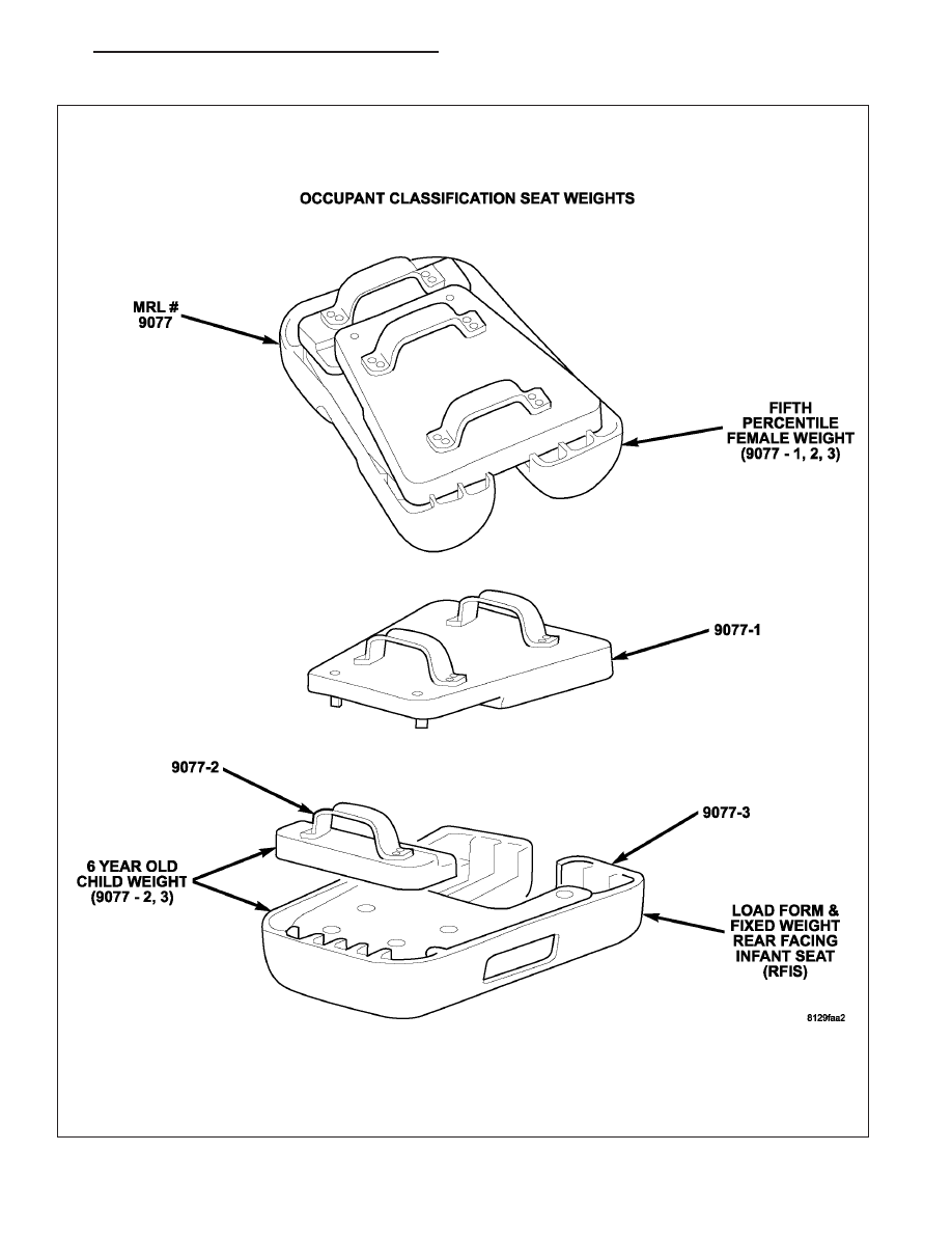
*DIAGNOSIS AND CHECKOUT PROCEDURE FOR SEAT WEIGHT SENSORS
OCS SEAT WEIGHTS MRL #9077
ND
RESTRAINTS - ELECTRICAL DIAGNOSTICS
8O - 391
Нет комментариевНе стесняйтесь поделиться с нами вашим ценным мнением.
Текст