Dodge Dakota (ND). Manual — part 825
•
Cylinder head(s) (Refer to 9 - ENGINE/CYLINDER HEAD - INSTALLATION).
•
Timing chain and cover (Refer to 9 - ENGINE/VALVE TIMING/TIMING BELT/CHAIN AND SPROCKETS -
INSTALLATION).
•
Cylinder head covers (Refer to 9 - ENGINE/CYLINDER HEAD/CYLINDER HEAD COVER(S) - INSTALLA-
TION).
•
Oil pan and gasket/windage tray. (Refer to 9 - ENGINE/LUBRICATION/OIL PAN - INSTALLATION).
11. Fill crankcase with proper engine oil to correct level.
12. Connect negative cable to battery.
RINGS-PISTON
STANDARD PROCEDURE
PISTON RING FITTING
Before reinstalling used rings or installing new rings,
the ring clearances must be checked.
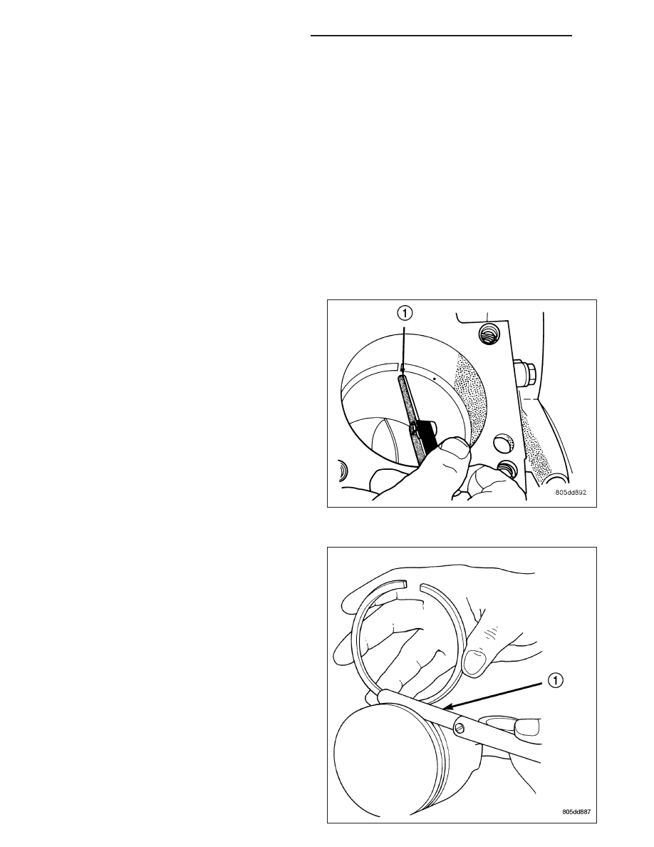
1. Wipe the cylinder bore clean.
2. Insert the ring in the cylinder bore.
NOTE: The ring gap measurement must be made
with the ring positioned at least 12mm (0.50 inch.)
from bottom of cylinder bore.
3. Using a piston, to ensure that the ring is squared in
the cylinder bore, slide the ring downward into the
cylinder.
4. Using a feeler gauge (1), check the ring end gap.
Replace any rings not within specification.
PISTON RING SIDE CLEARANCE
NOTE: Make sure the piston ring grooves are
clean and free of nicks and burrs.
9 - 838
ENGINE - 3.7L SERVICE INFORMATION
ND
PISTON RING SPECIFICATION CHART
Ring Position
Groove Clearance
Maximum Clearance
Upper Ring
.051-.094 mm
0.11 mm
(0.0020-.0037 in.)
(0.004 in.)
Intermediate Ring
0.04-0.08 mm
0.10 mm
(0.0016-0.0031 in.)
(0.004 in.)
Oil Control Ring
.019-.229 mm
.25 mm
(Steel Rails)
(.0007-.0090 in.)
(0.010 in.)
Ring Position
Ring Gap
Wear Limit
Upper Ring
0.20-0.36 mm
0.43 mm
(0.0079-0.0142 in.)
(0.0017 in.)
Intermediate Ring
0.37-0.63 mm
0.74 mm
(0.0146-0.0249 in.)
(0.029 in.)
Oil Control Ring
0.025-0.76 mm
1.55 mm
(Steel Rail)
(0.0099- 0.03 in.)
(0.061 in.)
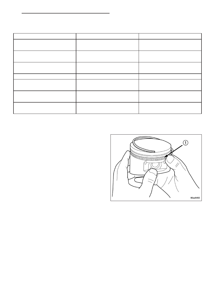
5. Measure the ring side clearance as shown make sure the feeler gauge (1) fits snugly between the ring land and
the ring. Replace any ring not within specification.
6. Rotate the ring around the piston, the ring must
rotate in the groove with out binding.
7. The No. 1 and No. 2 piston rings have a different
cross section. Ensure No. 2 ring is installed with
manufacturers I.D. mark (Dot) facing up, towards
top of the piston.
NOTE: Piston rings are installed in the following
order:
•
Oil ring expander.
•
Upper oil ring side rail (1).
•
Lower oil ring side rail.
•
No. 2 Intermediate piston ring.
•
No. 1 Upper piston ring.
8. Install the oil ring expander.
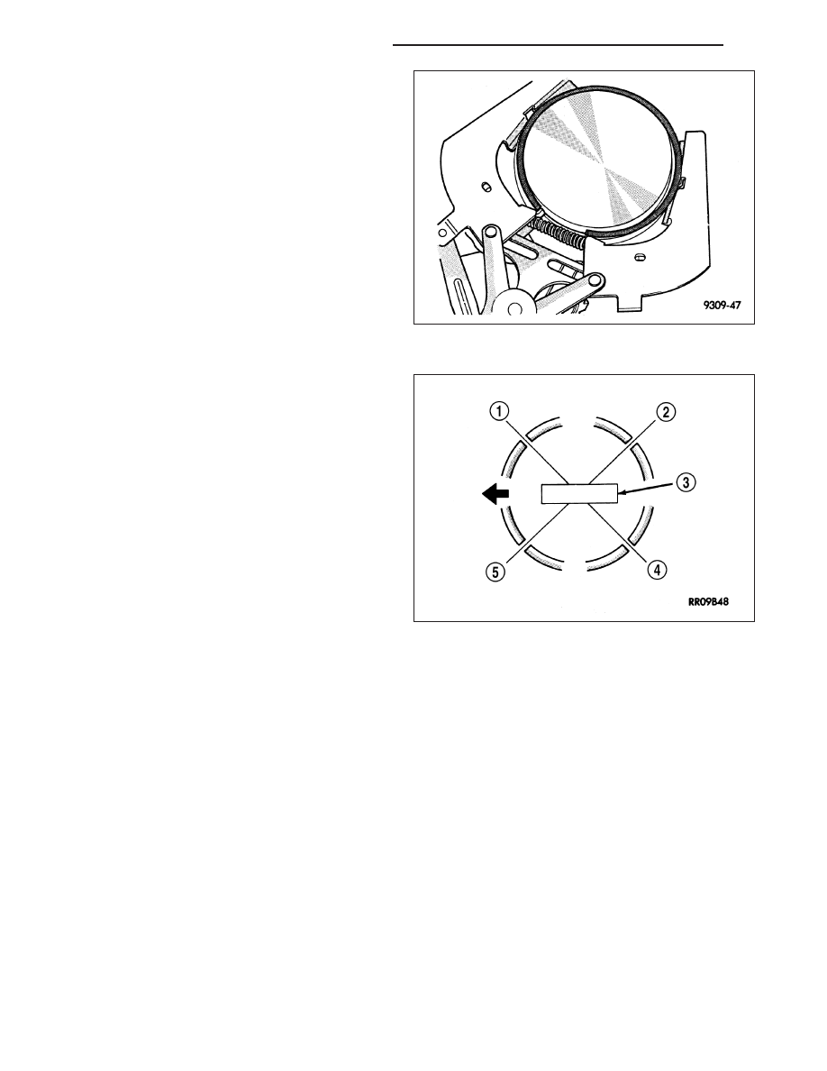
9. Install upper side rail by placing one end between the piston ring groove and the expander ring. Hold end firmly
and press down the portion to be installed until side rail is in position. Repeat this step for the lower side rail.
ND
ENGINE - 3.7L SERVICE INFORMATION
9 - 839
10. Install No. 2 intermediate piston ring using a pis-
ton ring installer.
11. Install No. 1 upper piston ring using a piston ring
installer.
12. Position piston ring end gaps as shown in. It is
important that expander ring gap is at least 45°
from the side rail gaps, but not on the piston pin
center or on the thrust direction.
9 - 840
ENGINE - 3.7L SERVICE INFORMATION
ND
DAMPER-CRANKSHAFT
REMOVAL
1. Disconnect negative cable from battery.
2. Remove radiator fan (Refer to 7 - COOLING/EN-
GINE/RADIATOR FAN - REMOVAL).
3. Remove accessory drive belt (Refer to 7 - COOL-
ING/ACCESSORY
DRIVE/DRIVE
BELTS
-
REMOVAL).
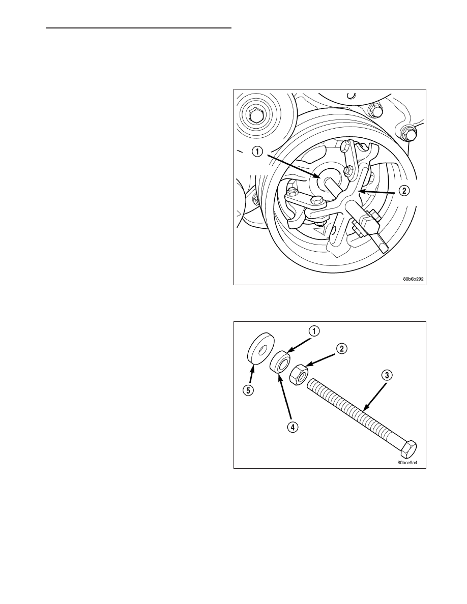
4. Remove crankshaft damper bolt.
5. Remove damper using Special Tools 8513 Insert
(1) and 1026 Three Jaw Puller (2).
INSTALLATION
CAUTION: To prevent severe damage to the Crank-
shaft, Damper or Special Tool 8512–A, thoroughly
clean the damper bore and the crankshaft nose
before installing Damper.
1. Align crankshaft damper slot with key in crankshaft.
Slide damper onto crankshaft slightly.
CAUTION: Special Tool 8512–A, is assembled in a
specific sequence. Failure to assemble this tool in
this sequence can result in tool failure and severe
damage to either the tool or the crankshaft.
2. Assemble Special Tool 8512–A as follows, The nut
(2) is threaded onto the threaded rod (3) first. Then
the roller bearing (1) is placed onto the threaded
rod (The hardened bearing surface of the bearing
MUSTface the nut (4) ). Then the hardened washer (5) slides onto the threaded rod. Once assembled coat the
threaded rod’s threads with Mopar
T
Nickel Anti-Seize or equivalent.
ND
ENGINE - 3.7L SERVICE INFORMATION
9 - 841
Нет комментариевНе стесняйтесь поделиться с нами вашим ценным мнением.
Текст