Dodge Dakota (ND). Manual — part 9
STANDARD PROCEDURE
HEIGHT MEASUREMENT
The vehicle suspension height MUST be measured and adjusted before performing wheel alignment procedure.
Also when front suspension components have been replaced. This measure must be performed with the vehicle
supporting it’s own weight and taken on both sides of the vehicle.
FRONT RIDE HEIGHT MEASUREMENT
1. Inspect tires and set to correct pressure.
2. Jounce the front of the vehicle.
3. With vehicle on level ground or hoist, make the following measurements:
a. Front wheel spindle (center) to ground vertical distance.
b. Measure the center of front face of bolt on the rear leg of lower control arm and the center of front face of
front leg of control arm to ground vertical distance and take the average height.
c. Difference between spindle and control arm bolt to ground average distance should be 71mm+/- 6mm. Note
that the control arm bolt is lower than the spindle.
4. After making any ride height adjustment, roll vehicle preferably jouncing it also, to relieve camber Effects and
then re-measure Lower control arm bolt to ground height.
5. Repeat the previous steps until the ride height is within specifications.
REAR RIDE HEIGHT MEASUREMENT
1. Inspect tires and set to correct pressure.
2. Jounce the front of the vehicle.
3. With vehicle on level ground or hoist, make the following measurements:
a. Distance from the landing pad of the jounce bumper on the axle side to the jounce bumper cup lip of the
frame side.
b. The difference between the jounce bumper landing pad and the jounce bumper cup lip the reading should be
148 mm +/-10 mm for 9.25
9
axle, 154 mm +/-10 mm for 8.25
9
axle.
TOE ADJUSTMENT
SUSPENSION HEIGHT MESUREMENT MUST BE
PERFORMED BEFORE AN ALIGNMENT.
The wheel toe position adjustment is the final adjust-
ment.
1. Start the engine and turn wheels both ways before
straightening the wheels. Secure the steering
wheel with the front wheels in the straight-ahead
position.
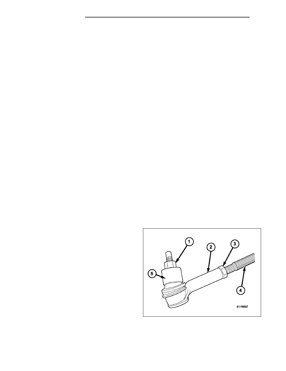
2. Loosen the tie rod jam nuts (3).
NOTE: Each front wheel should be adjusted for
one-half of the total toe position specification.
This will ensure the steering wheel will be cen-
tered when the wheels are positioned straight-
ahead.
3. Adjust the wheel toe position by turning the inner tie rod (4) as necessary.
4. Tighten the tie rod jam nut (3) to 75 N·m (55 ft. lbs.).
5. Verify the specifications.
6. Turn off engine.
2 - 4
WHEEL ALIGNMENT
ND
CAMBER, CASTER AND TOE ADJUSTMENT
Camber and caster angle adjustments involve changing the position of the lower control arm with the slots in the
frame brackets to move the lower control arm inwards or outwards for proper adjustment. This can be achieved by
using a socket on the head of the cam bolt and turning clockwise or counterclockwise to achieve the
proper specification.
NOTE: Both front and rear lower control arm cam bolts are adjustable.
NOTE: Camber and caster adjustments must be made at the lower control arm The upper control arm is not
adjustable.
NOTE: When the lower control arm cam bolts are loosened the lower control arm will normally go outwards
automatically with the weight of the vehicle.
CASTER
Moving the rear position of the lower control arm at the frame in or out, will change the caster angle significantly
and camber angle only slightly. To maintain the camber angle while adjusting caster, move the rear of the lower
control arm in or out. Then move the front of the lower control arm slightly in the opposite direction.
CAMBER
Move both the front and rear of the lower control arm together in or out. This will change the camber angle signif-
icantly and caster angle slightly.
After adjustment is made tighten the lower control arm bolt & nuts to 203 N·m (150 ft. lbs.).
TOE ADJUSTMENT
The wheel toe position adjustment is the final adjust-
ment.
1. Start the engine and turn wheels both ways before
straightening the wheels. Secure the steering
wheel with the front wheels in the straight-ahead
position.
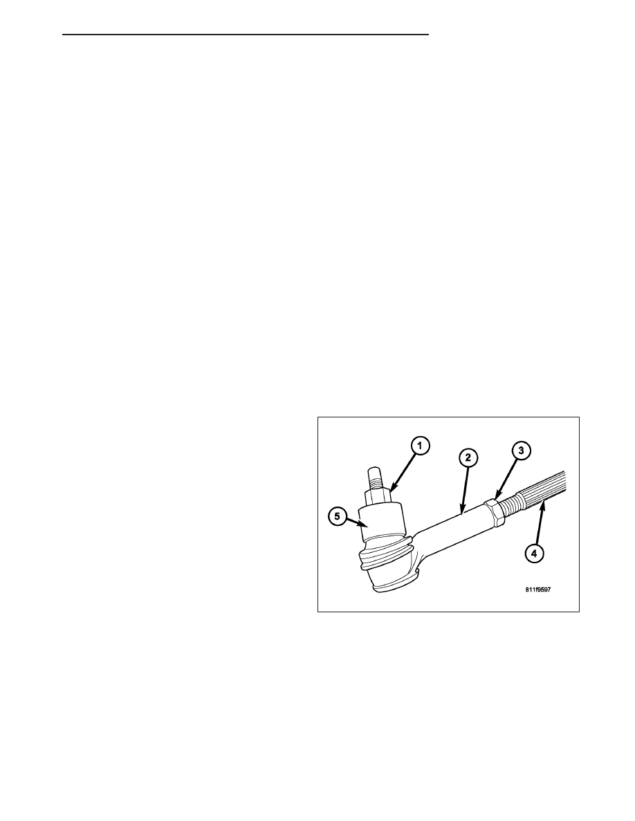
2. Loosen the tie rod jam nuts (3).
NOTE: Each front wheel should be adjusted for
one-half of the total toe position specification.
This will ensure the steering wheel will be cen-
tered when the wheels are positioned straight-
ahead.
3. Adjust the wheel toe position by turning the inner
tie rod (4) as necessary.
4. Tighten the tie rod jam nut (3) to 75 N·m (55 ft. lbs.).
5. Verify the specifications.
6. Turn off engine.
ND
WHEEL ALIGNMENT
2 - 5

SPECIFICATIONS
ALIGNMENT
NOTE: All alignment specifications are in degrees.
SPECIFICATIONS
DESCRIPTION
SPECIFICATION
VEHICLE
WHEEL BASE
CASTER
CAMBER
TOTAL TOE-IN
ALL
131 in
3.5 ± .05°
.25° ± .50°
.20° ± .05°
MAX RT/LT
DIFFERENCE
—
-.20° ± .50°
0° ± .50°
0.05° ± 0.05°
DESCRIPTION
REAR SPECIFICATION
CAMBER
(-.10° ± 0.35°)
TOTAL TOE-IN
(0.30° ± 0.35°)
THRUST ANGLE 0° ± 0.4°
2 - 6
WHEEL ALIGNMENT
ND
FRONT
TABLE OF CONTENTS
page
page
FRONT
. . . . . . . . . . . . . . . . . . . . . . . . . 7
. . . . . . . . . . . . . . . . . . . . . . . 8
. . . . . . . . . . . . . . . . . . . . . . . 8
. . . . . . . . . . . . . . . . . . . 9
BUSHINGS
. . . . . . . . . . . . . . . . . . . . . . . . . 11
LOWER CONTROL ARM SHOCK BUSHING
LOWER CONTROL ARM SHOCK BUSHING
HUB / BEARING
. . . . . . . . . . . . . . . . . . . . . . . . . . . . . 15
. . . . . . . . . . . . . . . . . . . . . . . . . 16
KNUCKLE
. . . . . . . . . . . . . . . . . . . . . . . . . 16
. . . . . . . . . . . . . . . . . . . . . . . . . . . 17
. . . . . . . . . . . . . . . . . . . . . . . . . . . . . 17
. . . . . . . . . . . . . . . . . . . . . . . . . 19
LOWER BALL JOINT
. . . . . . . . . . . . . . . . . . . 21
. . . . . . . . . . . . . . . . . . . . . . . . . . . . . 21
. . . . . . . . . . . . . . . . . . . . . . . . . 24
LOWER CONTROL ARM
. . . . . . . . . . . . . . . . . . . . . . . . . . . . . 25
. . . . . . . . . . . . . . . . . . . . . . . . . 28
SHOCK
. . . . . . . . . . . . . . . . . . . . . . . . . . . . . 30
. . . . . . . . . . . . . . . . . . . . . . . . . . . . . 31
. . . . . . . . . . . . . . . . . . . . . . . . . 32
SPRING
. . . . . . . . . . . . . . . . . . . . . . . . . . . . . 33
. . . . . . . . . . . . . . . . . . . . . . . . . 33
STABILIZER BAR
. . . . . . . . . . . . . . . . . . . . . . . . . 34
. . . . . . . . . . . . . . . . . . . . . . . . . . . 34
. . . . . . . . . . . . . . . . . . . . . . . . . . . . . 35
. . . . . . . . . . . . . . . . . . . . . . . . . 35
STABILIZER LINK
. . . . . . . . . . . . . . . . . . . . . . . . . . . . . 36
. . . . . . . . . . . . . . . . . . . . . . . . . 36
UPPER BALL JOINT
. . . . . . . . . . . . . . . . . . . 37
UPPER CONTROL ARM
. . . . . . . . . . . . . . . . . . . . . . . . . . . . . 37
. . . . . . . . . . . . . . . . . . . . . . . . . 38
FRONT
DESCRIPTION
SUSPENSION
The front suspension is designed to allow each wheel to adapt to different road surfaces independently. The wheels
are mounted to hub/bearings units bolted to the steering knuckle. The double-row hub bearings are sealed and
lubricated for life. The steering knuckles turn (pivot) on ball joints.
The front suspension is comprised of :
•
Shock absorbers
•
Control arms
•
Steering knuckles
•
Stabilizer bar
•
Stabilizer link
•
Tie Rod Ends
•
Hub/Bearing
•
Rack & Pinion
•
Ball Joints
ND
FRONT
2 - 7
Нет комментариевНе стесняйтесь поделиться с нами вашим ценным мнением.
Текст