Dodge Dakota (ND). Manual — part 891
LOOSE STEERING AND VEHICLE LEAD
CONDITION
POSSIBLE CAUSE
CORRECTION
EXCESSIVE PLAY IN STEERING
WHEEL
1. Worn or loose suspension or
steering components.
1. Inspect and repair as necessary.
2. Worn or loose wheel bearings.
2. Inspect and repair or adjust
bearings.
3. Steering gear mounting.
3. Tighten gear mounting bolts to
specification.
4. Gear out of adjustment.
4. Replace gear.
5. Worn or loose steering coupler.
5. Inspect and replace as
necessary.
VEHICLE PULLS OR LEADS TO
ONE SIDE.
1. Tire Pressure.
1. Adjust tire pressure.
2. Radial tire lead.
2. Rotate tires.
3. Brakes dragging.
3. Repair as necessary.
4. Wheel alignment.
4. Align front end.
POWER STEERING FLOW AND PRESSURE
The following procedure is used to test the operation
of the power steering system on the vehicle. This test
will provide the gallons per minute (GPM) or flow rate
of the power steering pump along with the maximum
relief pressure. Perform test any time a power steering
system problem is present. This test will determine if
the power steering pump or power steering gear is not
functioning properly. The following pressure and flow
test is performed using Power Steering Analyzer Tool
kit 6815 (3) Adapter Kit 6893 and 6825A.
FLOW AND PRESSURE TEST
1. Check the power steering belt to ensure it is in
good condition and adjusted properly.
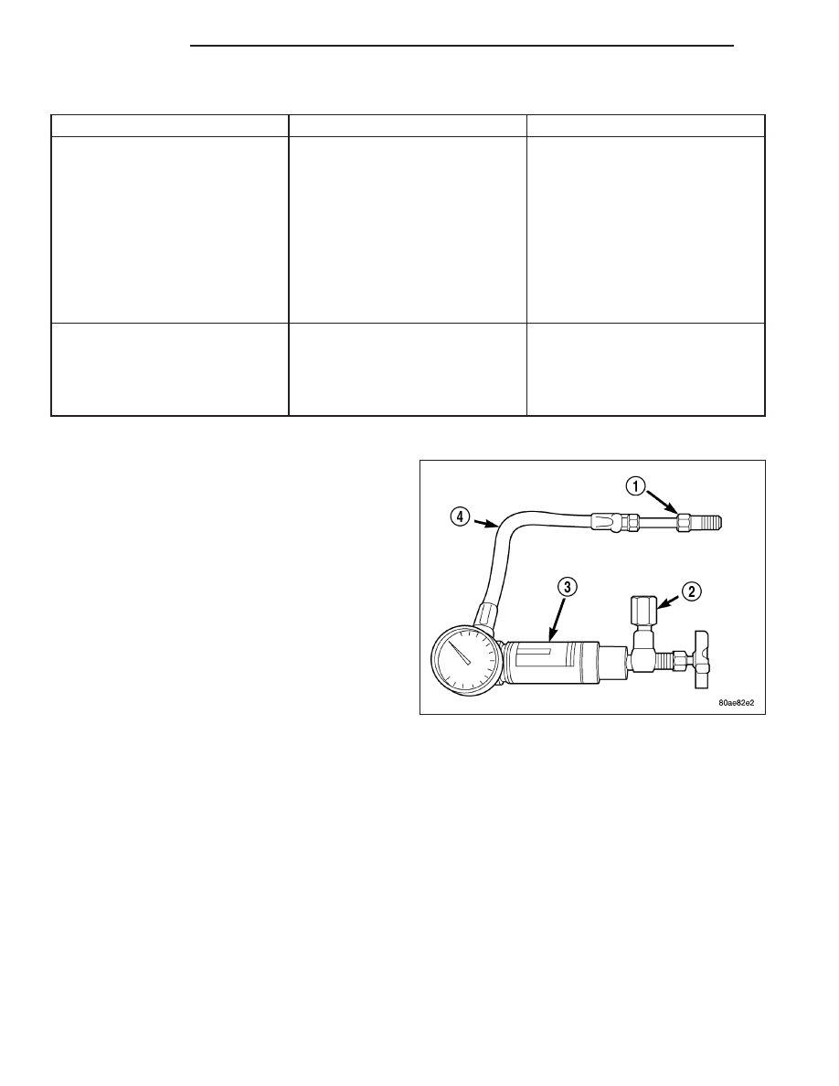
2. Connect pressure gauge hose from the Power
Steering Analyzer to Tube 6825A.
3. Connect Adapter 6826 to Power Steering Analyzer test valve end.
4. Disconnect the high pressure hose from the power steering pump.
5. Connect the tube to the pump hose fitting.
6. Connect the power steering hose from the steering gear to the adapter.
7. Open the test valve completely.
8. Start engine and let idle long enough to circulate power steering fluid through flow/pressure test gauge and to get
air out of the fluid. Then shut off engine.
9. Check fluid level, add fluid as necessary. Start engine again and let idle.
10. Gauge should read below 862 kPa (125 psi), if above, inspect the hoses for restrictions and repair as neces-
sary. The initial pressure reading should be in the range of 345-552 kPa (50-80 psi).
11. Increase the engine speed to 1500 RPM and read the flow meter. If the flow rate (GPM) is below specification,
(refer to pump specification chart for GPM) the pump should be replaced.
CAUTION: The following test procedure involves testing maximum pump pressure output and flow control
valve operation. Do not leave valve closed for more than three seconds as the pump could be damaged.
19 - 4
STEERING
ND
12. Close valve fully three times and record highest pressure indicated each time. All three readings must be
above specifications and within 345 kPa (50 psi) of each other.
•
Pressures above specifications but not within 345 kPa (50 psi) of each other, replace pump.
•
Pressures within 345 kPa (50 psi) of each other but below specifications, replace pump.
13. Open the test valve and turn the steering wheel to the extreme left and right positions three times against the
stops. Record the highest pressure reading at each position. Compare readings to the pump specifications
chart. If pressures readings are not within 50 psi of each other, the gear is leaking internally and must be
replaced.
CAUTION: Do not force the pump to operate against the stops for more than 2 to 3 seconds at a time
because, pump damage will result.
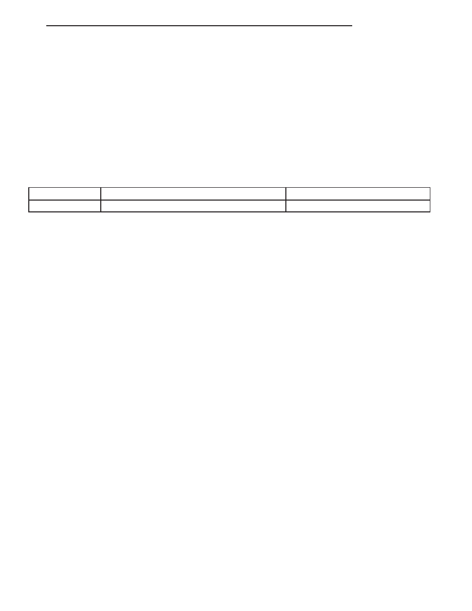
PUMP SPECIFICATION
ENGINE
RELIEF PRESSURE ± 50
FLOW RATE (GPM) AT 1500 RPM
All
11652 kPa (1690 psi)
2.6
ND
STEERING
19 - 5
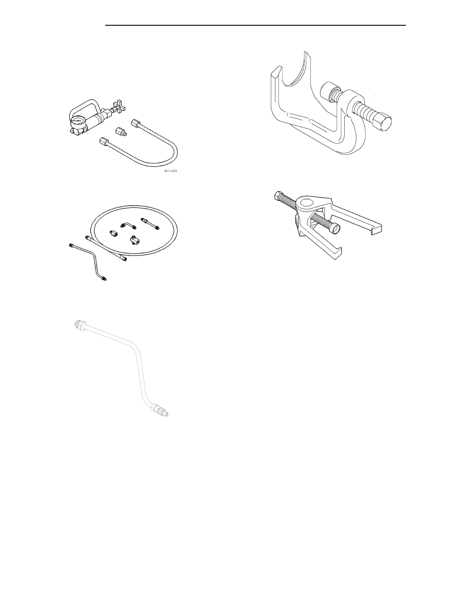
SPECIAL TOOLS
POWER STEERING PUMP
Analyzer Set, Power Steering Flow/Pressure 6815
Adapters, Power Steering Flow/Pressure Tester 6893
ADAPTER, POWER STEERING FLOW/PRESSURE -
6825A
PULLER - 8677
19 - 6
STEERING
ND
COLUMN
TABLE OF CONTENTS
page
page
COLUMN
. . . . . . . . . . . . . . . . . . . . . . . . . . 7
. . . . . . . . . . . . . . . . . . . . 8
. . . . . . . . . . . . . . . . . . . . . . . . . . . . . . 8
. . . . . . . . . . . . . . . . . . . . . . . . . 12
. . . . . . . . . . . . . . . . . . . . . . 16
SWITCH-IGNITION
. . . . . . . . . . . . . . . . . . . . . . . . . 16
. . . . . . . . . . . . . . . . . . . . . . . . . . . 16
. . . . . . . . . . . . . . . . . . . . 17
. . . . . . . . . . . . . . . . . . . . . . . . . . . . . 17
. . . . . . . . . . . . . . . . . . . . . . . . . 18
SWITCH-KEY-IN IGNITION
. . . . . . . . . . . . . . . . . . . . . . . . . 20
CYLINDER . . . . . . . . . . . . . . . . . . . . . . . . . . . 20
KEY/LOCK CYLINDER
. . . . . . . . . . . . . . . . . . . . . . . . . . . . . 21
. . . . . . . . . . . . . . . . . . . . . . . . . 21
GEAR SHIFT LEVER
. . . . . . . . . . . . . . . . . . . . . . . . . . . . . 22
. . . . . . . . . . . . . . . . . . . . . . . . . 22
STEERING WHEEL
. . . . . . . . . . . . . . . . . . . . . . . . . . . . . 23
. . . . . . . . . . . . . . . . . . . . . . . . . 24
STEERING COUPLING SHAFT
. . . . . . . . . . . . . . . . . . . . . . . . . . . . . 25
. . . . . . . . . . . . . . . . . . . . . . . . . 26
LOWER STEERING COUPLING
. . . . . . . . . . . . . . . . . . . . . . . . . . . . . 27
. . . . . . . . . . . . . . . . . . . . . . . . . 28
TILT LEVER KNOB RELEASE
. . . . . . . . . . . . . . . . . . . . . . . . . . . . . 28
. . . . . . . . . . . . . . . . . . . . . . . . . 30
COLUMN
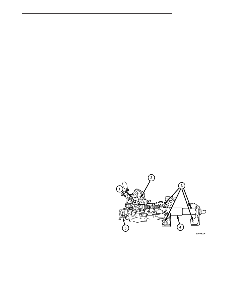
DESCRIPTION
NOTE: The steering column on vehicles with an
automatic transmission may not be equipped with
an internal locking shaft that allows the ignition
key cylinder to be locked with the key. Alternative
methods of locking the steering wheel for service
will have to be used.
The tilt and standard column (4) has been designed to
be serviced as an assembly; less wiring, switches,
shrouds, steering wheel, etc. Most steering column
components can be serviced without removing the
steering column from the vehicle.
To service the steering wheel, switches or airbag, refer
to
Restraints
and
follow
all
WARNINGS
and
CAUTIONS.
ND
COLUMN
19 - 7
Нет комментариевНе стесняйтесь поделиться с нами вашим ценным мнением.
Текст