Dodge Dakota (ND). Manual — part 82

C123B-EXCESSIVE DUMP FAULT (EBC125)
For a complete wiring diagram Refer to Section 8W.
•
When Monitored:
Ignition on.
•
Set Condition:
If more than 16 dump pulses in a row are detected without wheel speed recovery, this DTC will be set to
active.
Possible Causes
INTERMITTENT EXCESSIVE DUMP TIME DTC
WHEEL SPEED WIRING HARNESS AND CONNECTORS
SUSPENSION
TONE WHEEL
WHEEL BEARING
BRAKE SYSTEM MECHANICAL CONDITION
ANTI-LOCK BRAKE HYDRAULIC CONTROL UNIT
Diagnostic Test
1.
BRAKE SYSTEM MECHANICAL CONDITION
Inspect the front and rear brakes for a mechanical condition that would cause any wheel(s) to lock-up during brak-
ing.
Inspect the Parking Brake to make sure it releases properly.
Were any problems found?
Yes
>> Repair the braking system as necessary in accordance with the Service Information.
Perform ABS VERIFICATION TEST - VER 1. (Refer to 5 - BRAKES/ELECTRICAL - DIAGNOSIS AND
TESTING)
No
>> Go To 2
2.
TONE WHEEL
Inspect each Tone Wheel for damage, missing teeth or looseness in accordance with the Service Information.
NOTE: The Tone Wheel Teeth should be perfectly square, not bent or nicked.
Were any problems found?
Yes
>> Replace the Tone Wheel as necessary in accordance with the Service Information.
Perform ABS VERIFICATION TEST - VER 1. (Refer to 5 - BRAKES/ELECTRICAL - DIAGNOSIS AND
TESTING)
No
>> Go To 3
5 - 98
BRAKES - ABS ELECTRICAL DIAGNOSTICS
ND
C123B-EXCESSIVE DUMP FAULT (EBC125) (CONTINUED)
3.
WHEEL BEARING
Inspect each wheel bearing for excessive run out or improper clearance in accordance with the Service Information.
Were any problems found?
Yes
>> Repair or replace the wheel bearing(s) as necessary in accordance with the Service Information.
Perform ABS VERIFICATION TEST - VER 1. (Refer to 5 - BRAKES/ELECTRICAL - DIAGNOSIS AND
TESTING)
No
>> Go To 4
4.
WHEEL SPEED SENSOR WIRING HARNESS AND CONNECTORS
Start the engine.
With the scan tool, monitor the output of each Wheel Speed Sensor.
Raise and properly support the vehicle.
WARNING: BE SURE TO KEEP HANDS, FEET AND CLOTHING CLEAR OF ROTATING COMPONENTS.
Allow the drive wheels to rotate.
Rotate the non-driven wheels by hand.
Wiggle test the Wheel Speed wiring harnesses and connectors.
Look for any excessive variations in sensed wheel speed.
Were any problems found?
Yes
>> Repair the wiring harness or connectors as necessary in accordance with the Service Information.
Perform ABS VERIFICATION TEST - VER 1. (Refer to 5 - BRAKES/ELECTRICAL - DIAGNOSIS AND
TESTING)
No
>> Go To 5
5.
LOADED WHEEL BEARING/SUSPENSION CONCERN
CAUTION: Make sure that the vehicle has braking capability before performing a road test.
NOTE: Have an assistant drive the vehicle while monitoring the scan tool.
With the scan tool, monitor the output of each Wheel Speed Sensor.
Road test vehicle so wheel bearings and suspension are loaded.
Look for any excessive variations in sensed wheel speed.
Were any problems found?
Yes
>> Repair as necessary in accordance with the Service Information.
Perform ABS VERIFICATION TEST - VER 1. (Refer to 5 - BRAKES/ELECTRICAL - DIAGNOSIS AND
TESTING)
No
>> Replace the Hydraulic Control Unit in accordance with the Service Information.
Perform ABS VERIFICATION TEST - VER 1. (Refer to 5 - BRAKES/ELECTRICAL - DIAGNOSIS AND
TESTING)
ND
BRAKES - ABS ELECTRICAL DIAGNOSTICS
5 - 99

C2100-BATTERY VOLTAGE LOW (EBC125)
5 - 100
BRAKES - ABS ELECTRICAL DIAGNOSTICS
ND
C2100-BATTERY VOLTAGE LOW (EBC125) (CONTINUED)
For a complete wiring diagram Refer to Section 8W.
•
When Monitored:
Ignition on.
•
Set Condition:
If the sensed ignition voltage drops below 9.0 volts (+/- 10%) for 100 msec.
Possible Causes
INTERMITTENT BATTERY VOLTAGE LOW DTC
(F500) FUSED RUN RELAY OUTPUT CIRCUIT OPEN OR HIGH RESISTANCE
(Z107) GROUND CIRCUIT OPEN OR HIGH RESISTANCE
ANTI-LOCK BRAKE MODULE
Diagnostic Test
1.
DTC IS ACTIVE
NOTE: Diagnose and repair any powertrain Charging system DTCs before continuing with this procedure.
NOTE: Ensure the battery is fully charged.
Turn the ignition on.
With the Scan tool, select View DTCs in the Anti-lock Brake Module. Record all DTC information.
Turn the ignition off.
Start the engine.
With the Scan tool read DTCs.
Is the status Active for this DTC?
Yes
>> Go To 2
No
>> Go To 4
2.
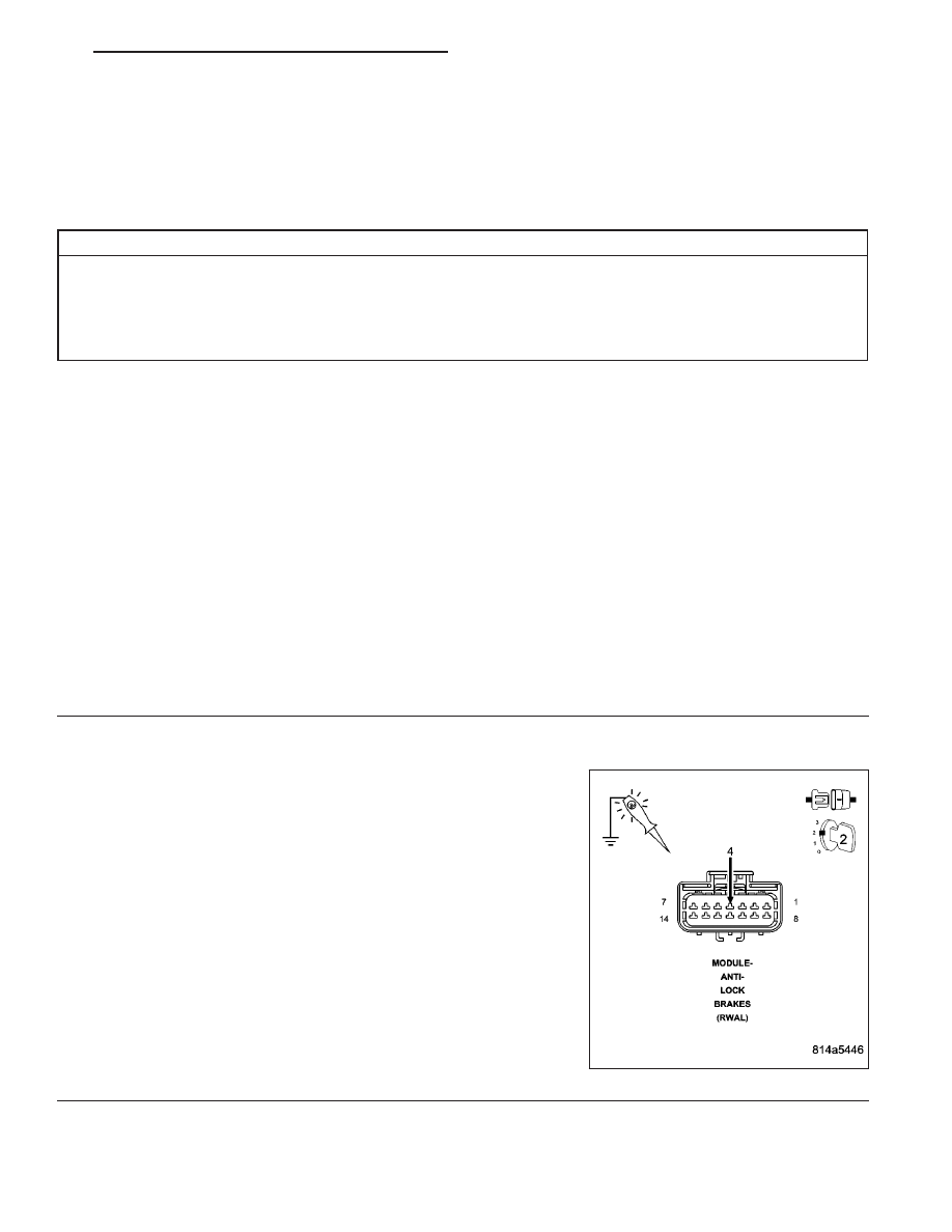
(F500) FUSED RUN RELAY OUTPUT CIRCUIT OPEN OR HIGH RESISTANCE
Turn the ignition off.
Disconnect the Anti-lock Brake Module harness connector.
Check connectors - Clean/repair as necessary.
Turn the ignition on.
Using a 12–volt test light connected to ground, check the (F500)
Fused Run Relay Output circuit.
NOTE: The test light should be illuminated and bright. Compare
the brightness to that of a direct connection to the battery.
Is the test light illuminated and bright?
Yes
>> Go To 3
No
>> Repair the (F500) Fused Run Relay Output circuit for an
open circuit or high resistance.
Perform ABS VERIFICATION TEST - VER 1. (Refer to 5 -
BRAKES/ELECTRICAL - DIAGNOSIS AND TESTING)
ND
BRAKES - ABS ELECTRICAL DIAGNOSTICS
5 - 101
Нет комментариевНе стесняйтесь поделиться с нами вашим ценным мнением.
Текст