Dodge Dakota (ND). Manual — part 151
B1488–CABIN EQ MISMATCH PERFORMANCE
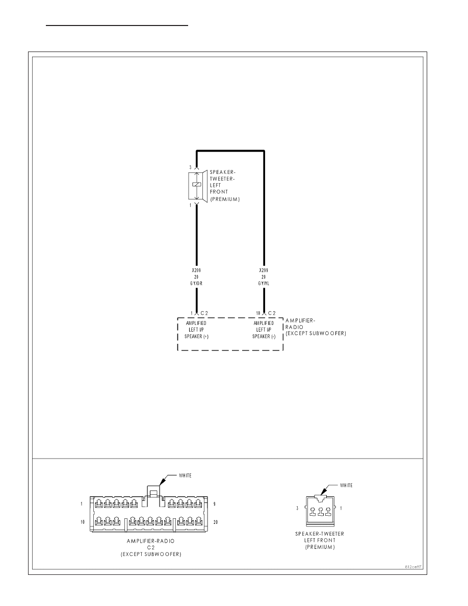
For the Amplifier circuit diagram (Refer to 8 - ELECTRICAL/AUDIO - SCHEMATICS AND DIAGRAMS).
For a complete wiring diagram Refer to Section 8W.
•
When Monitored:
With the ignition on.
•
Set Condition:
If the cabin EQ message is incompatible with the EQ’s stored in the amplifier for 10 consecutive cycles, then
the amplifier will set this DTC.
POSSIBLE CAUSES
NO COMMUNICATION WITH FRONT CONTROL MODULE
ACTIVE FCM DTCs
AMPLIFIER
Diagnostic Test
1.
CHECK FOR AN INTERMITTENT CONDITION
Turn the ignition on.
Turn the radio on.
With the scan tool, erase Amplifier DTCs.
With the scan tool, reset the amplifier.
With the scan tool, read Amplifier DTCs.
Does the scan tool display active: B1488–CABIN EQ MISMATCH
PERFORMANCE?
Yes
>> Go To 2
No
>> The conditions that caused this code to set are not
present at this time. Using the wiring diagram/schematic
as a guide, inspect the wiring and connectors.
Perform BODY VERIFICATION TEST VER-1.
2.
CHECK AMPLIFIER BUSSED INPUTS/OUTPUTS
With the scan tool in Amplifier Data Display, read the Cabin EQ# settings in the Bussed Inputs and Bussed Outputs
Sections.
NOTE: The Cabin EQ# settings in the Inputs/Outputs section should match one another. The Cabin EQ# in
the Inputs section is the information that is received form the FCM. The Cabin EQ# in the Outputs section
is the information that is Stored in the Amplifier’s memory.
The Cabin EQ# settings are as follows:
• •
$51: HB Premium 1 (w/o Subwoofer)
• •
$52: HB Premium 2 (with Subwoofer)
Do the Cabin EQ# settings match one another?
Yes
>> Replace the Amplifier in accordance to the service information.
Perform the BODY VERIFICATION TEST-VER 1.
No
>> Go To 3
8A - 62
AUDIO/VIDEO SYSTEMS - ELECTRICAL DIAGNOSIS
ND
B1488–CABIN EQ MISMATCH PERFORMANCE (CONTINUED)
3.
VERIFY COMMUNICATION WITH FRONT CONTROL MODULE
With the scan tool in ECU VIEW, read active modules on the bus.
Does the scan tool show the Front Control Module active on the bus?
Yes
>> Go To 4
No
>> Refer to the Communication category for the related symptoms.
Perform the BODY VERIFICATION TEST VER 1.
4.
CHECK FRONT CONTROL MODULE FOR ACTIVE DTCs
With the scan tool, erase FCM DTCs.
Turn the ignition off. Wait approximately 10 seconds.
Turn the ignition on.
With the scan tool, read FCM DTCs.
Are any active DTCs present?
Yes
>> Refer to symptom list for problems related to the Front Control Module.
Perform the BODY VERIFICATION TEST VER 1.
No
>> Replace the Front Control Module in accordance with the Service Information.
Perform the BODY VERIFICATION TEST-VER.1
ND
AUDIO/VIDEO SYSTEMS - ELECTRICAL DIAGNOSIS
8A - 63
B1460-CHANNEL 1 AUDIO SPEAKER OUTPUT CIRCUIT PERFORMANCE
For a complete wiring diagram Refer to Section 8W.
•
When Monitored:
With the ignition on.
•
Set Condition:
This DTC will set if a DC offset occurs on the output channel, the amplifier shall set a DTC after a maturity
rate of 5 ±1 sec.
Possible Causes
AMPLIFIER
Diagnostic Test
1.
CHECK FOR AN INTERMITTENT CONDITION
Turn the ignition on, then off, and then on again.
With the scan tool, read Amplifier DTCs.
Does the scan tool display active: B1460-CHANNEL 1 AUDIO
SPEAKER OUTPUT CIRCUIT PERFORMANCE?
Yes
>> Replace the Amplifier in accordance with the service infor-
mation.
Perform BODY VERIFICATION TEST VER-1.
No
>> The conditions that caused this code to set are not
present at this time. Using the wiring diagram/schematic
as a guide, inspect the wiring and connectors.
Perform BODY VERIFICATION TEST VER-1.
8A - 64
AUDIO/VIDEO SYSTEMS - ELECTRICAL DIAGNOSIS
ND
B1461-CHANNEL 1 AUDIO SPEAKER OUTPUT CIRCUIT LOW
ND
AUDIO/VIDEO SYSTEMS - ELECTRICAL DIAGNOSIS
8A - 65
Нет комментариевНе стесняйтесь поделиться с нами вашим ценным мнением.
Текст