Dodge Dakota (ND). Manual — part 1304
PCM SYSTEM GROUND
The PCM cannot determine a poor system ground. However, one or more diagnostic trouble codes may be gener-
ated as a result of this condition. The module should be mounted to the body at all times, also during diagnostic.
PCM CONNECTOR ENGAGEMENT
The PCM may not be able to determine spread or damaged connector pins. However, it might store diagnostic
trouble codes as a result of spread connector pins.
25 - 10
EMISSIONS CONTROL
ND
EVAPORATIVE EMISSIONS
TABLE OF CONTENTS
page
page
EVAPORATIVE EMISSIONS
. . . . . . . . . . . . . . . 11
SOLENOID - EVAP/PURGE
. . . . . . . . . . . . . . . . . . . . . . . . . 12
. . . . . . . . . . . . . . . . . . . . . . . . . . . 12
. . . . . . . . . . . . . . . . . . . . . . . . . . . . . 12
. . . . . . . . . . . . . . . . . . . . . . . . . 13
CAP - FUEL FILLER
. . . . . . . . . . . . . . . . . . . . . . . . . 13
. . . . . . . . . . . . . . . . . . . . . . . . . . . 13
. . . . . . . . . . . . . . . 13
ORVR
. . . . . . . . . . . . . . . . . . . . . . . . . 13
. . . . . . . . . . . . . . . . . . . . . . . . . . . 14
VALVE - PCV
. . . . . . . . . . . . . . . . . . . . . . . . . 14
. . . . . . . . . . . . . . . . . . . . . . . . . . . 15
PCV VALVE - 3.7L V-6/ 4.7L V-8
. . . . . . . . . . . . . . . . . . . . . . . . . . . . . 18
. . . . . . . . . . . . . . . . . . . . . . . . . 18
LINES - VACUUM
. . . . . . . . . . . . . . . . . . . . . . . . . 18
CANISTER - VAPOR
. . . . . . . . . . . . . . . . . . . . . . . . . 19
. . . . . . . . . . . . . . . . . . . . . . . . . . . 19
. . . . . . . . . . . . . . . . . . . . . . . . . . . . . 20
. . . . . . . . . . . . . . . . . . . . . . . . . 21
PUMP-NATURAL VAC LEAK DETECTION
. . . . . . . . . . . . . . . . . . . . . . . . . 22
. . . . . . . . . . . . . . . . . . . . . . . . . . . 22
. . . . . . . . . . . . . . . . . . . . . . . . . . . . . 23
. . . . . . . . . . . . . . . . . . . . . . . . . 24
EVAPORATIVE EMISSIONS
SPECIFICATIONS
TORQUE - EVAP SYSTEM
DESCRIPTION
N·m
Ft. Lbs.
In. Lbs.
EVAP Canister Mounting
Nuts
11
-
95
EVAP Canister Mounting
Bracket-to-Frame Bolts
14
10
125
ND
EVAPORATIVE EMISSIONS
25 - 11
SOLENOID - EVAP/PURGE
DESCRIPTION
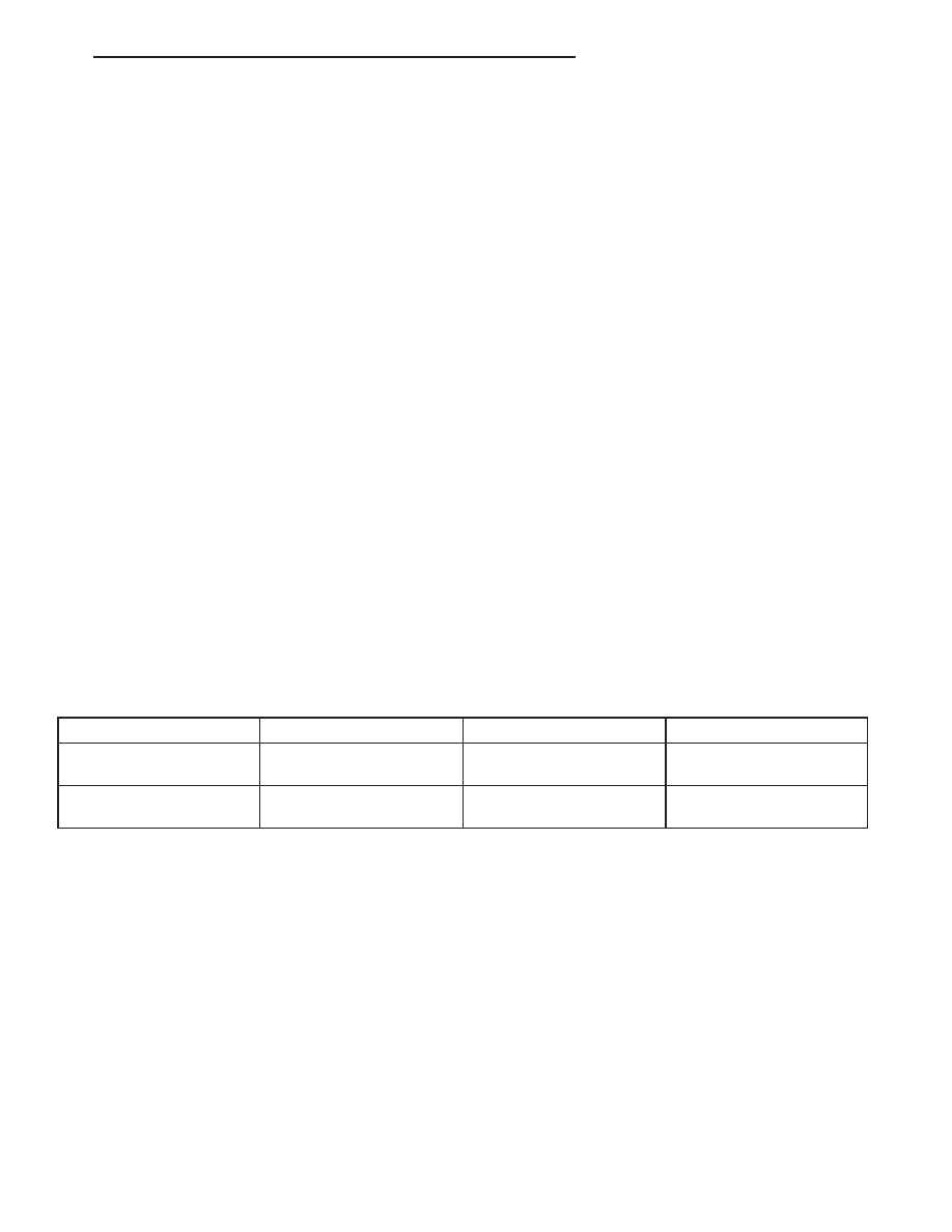
The duty cycle EVAP canister purge solenoid (2) is
located in the engine compartment. It is attached to a
bracket near the brake power booster (3).
OPERATION
The Powertrain Control Module (PCM) operates the solenoid.
During the cold start warm-up period and the hot start time delay, the PCM does not energize the solenoid. When
de-energized, no vapors are purged. The PCM de-energizes the solenoid during open loop operation.
The engine enters closed loop operation after it reaches a specified temperature and the time delay ends. During
closed loop operation, the PCM energizes and de-energizes the solenoid 5 or 10 times per second, depending upon
operating conditions. The PCM varies the vapor flow rate by changing solenoid pulse width. Pulse width is the
amount of time the solenoid energizes. The PCM adjusts solenoid pulse width based on engine operating condition.
REMOVAL
The duty cycle EVAP canister purge solenoid (2) is
located in the engine compartment. It is attached to a
bracket near the brake power booster (3).
1. Disconnect electrical wiring connector (1) at sole-
noid.
2. Disconnect vacuum hoses (4) at solenoid.
3. Remove solenoid from mounting bracket.
25 - 12
EVAPORATIVE EMISSIONS
ND
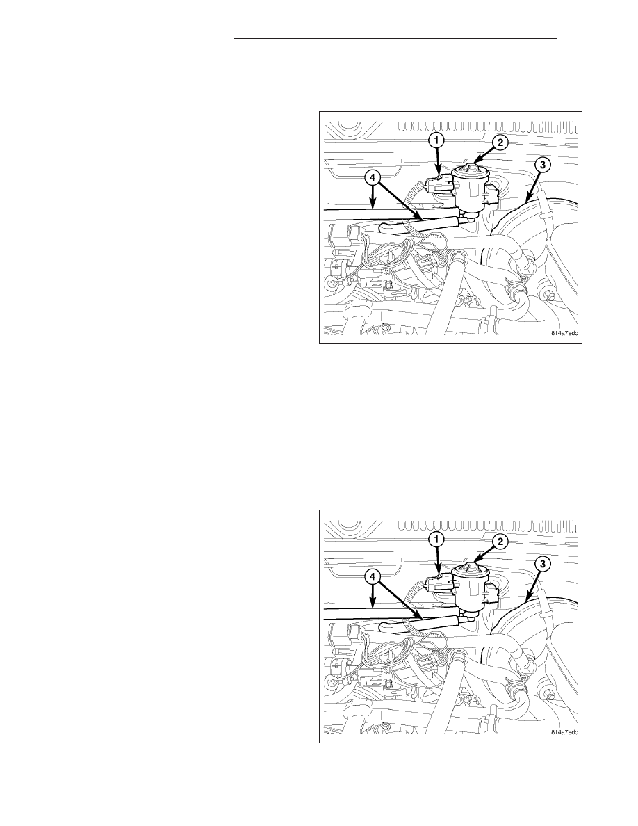
INSTALLATION
1. Install solenoid assembly (2) to mounting bracket.
2. Connect vacuum hoses (4).
3. Connect electrical connector (1).
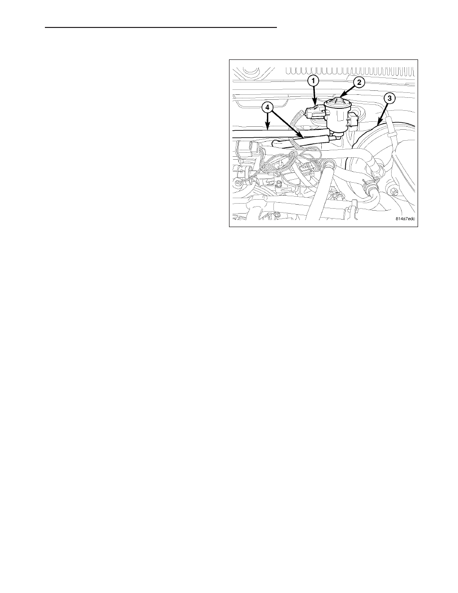
4.
The vapor/vacuum lines and hoses must be
firmly
connected.
Check
the
vapor/vacuum
lines at the NVLD pump, pump filter and EVAP
canister purge solenoid for damage or leaks. If
a leak is present, a Diagnostic Trouble Code
(DTC) may be set.
CAP - FUEL FILLER
DESCRIPTION
The plastic fuel tank filler tube cap is threaded onto the end of the fuel fill tube. Certain models are equipped with
a 1/4 turn cap.
OPERATION
The loss of any fuel or vapor out of fuel filler tube is prevented by the use of a pressure-vacuum fuel fill cap. Relief
valves inside the cap will release fuel tank pressure at predetermined pressures. Fuel tank vacuum will also be
released at predetermined values. This cap must be replaced by a similar unit if replacement is necessary. This is
in order for the system to remain effective.
CAUTION: Remove fill cap before servicing any fuel system component to relieve tank pressure. If equipped
with a Leak Detection Pump (LDP), or NVLD system, the cap must be tightened securely. If cap is left loose,
a Diagnostic Trouble Code (DTC) may be set.
REMOVAL
REMOVAL/INSTALLATION
If replacement of the 1/4 turn fuel tank filler tube cap is necessary, it must be replaced with an identical cap to be
sure of correct system operation.
CAUTION: Remove the fuel tank filler tube cap to relieve fuel tank pressure. The cap must be removed prior
to disconnecting any fuel system component or before draining the fuel tank.
ORVR
DESCRIPTION
The ORVR (On-Board Refueling Vapor Recovery) system consists of a unique fuel tank, flow management valve,
fluid control valve, one-way check valve and vapor canister.
ND
EVAPORATIVE EMISSIONS
25 - 13
Нет комментариевНе стесняйтесь поделиться с нами вашим ценным мнением.
Текст