Dodge Dakota (ND). Manual — part 108
C1073–ABS MOTOR CONTROL CIRCUIT (340) (CONTINUED)
For a complete wiring diagram Refer to Section 8W.
•
When Monitored:
With the ignition on and no system under voltage condition present.
•
Set Condition:
OPEN CIRCUIT: If pump motor feedback remains greater than 0.75 volts for more than 50 msec (+/- 5 msec)
after monitoring conditions are met, the DTC will set.
LOCKED MOTOR: If the module detects that the motor is spinning at less than 500 r.p.m. after monitoring
conditions are met, the DTC will set.
LOW VOLTAGE: The voltage of the supply is monitored every 3 msec. If the voltage is low for 150 msec, the
DTC will set.
Possible Causes
INTERMITTENT ABS MOTOR CONTROL CIRCUIT DTC
(A107) FUSED B+ CIRCUIT OPEN OR HIGH RESISTANCE
(Z107) OR (Z923) GROUND CIRCUIT OPEN OR HIGH RESISTANCE
ANTI-LOCK BRAKE MODULE
Diagnostic Test
1.
DTC IS ACTIVE
Turn the ignition on.
With the scan tool, clear DTCs.
Turn the ignition off.
Turn the ignition on.
With the scan tool, actuate the ABS pump motor.
Did the Pump Motor operate when actuated?
No
>> Go To 2
Yes
>> Go To 5
2.
(A107) FUSED B+ CIRCUIT OPEN OR HIGH RESISTANCE
Turn the ignition off.
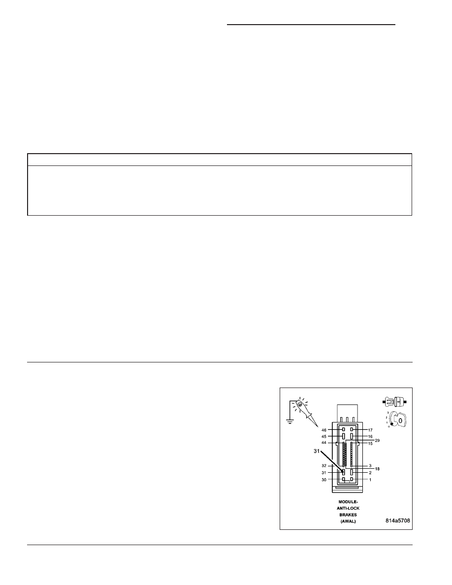
Disconnect the Anti-lock Brake Module harness connector.
NOTE: Note: Check connector - Clean/repair as necessary.
Using a 12–volt test light connected to ground, check the (A107)
Fused B+ Circuit.
NOTE: The test light should be illuminated and bright. Compare
the brightness to that of a direct connection to the battery.
Is the test light illuminated and bright?
Yes
>> Go To 3
No
>> Repair the (A107) Fused B+ Circuit for an open circuit or
high resistance.
Perform ABS VERIFICATION TEST - VER 1. (Refer to 5 -
BRAKES/ELECTRICAL - DIAGNOSIS AND TESTING)
5 - 202
BRAKES - ABS ELECTRICAL DIAGNOSTICS
ND
C1073–ABS MOTOR CONTROL CIRCUIT (340) (CONTINUED)
3.
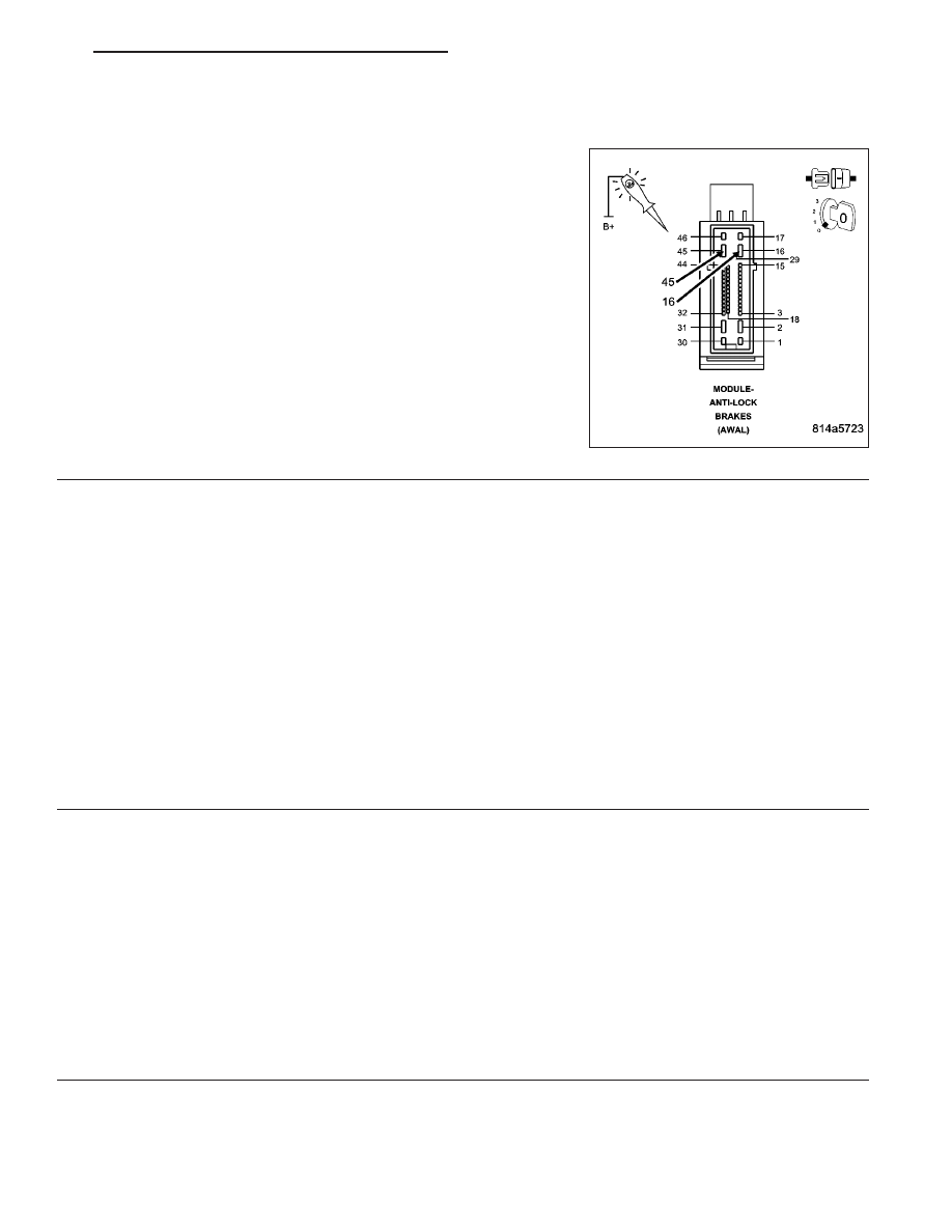
(Z107) or (Z923) GROUND CIRCUIT OPEN OR HIGH RESISTANCE
Using a 12–volt test light connected to 12–volts, check the (Z107) and
(Z923) Ground circuits.
NOTE: The test light should be illuminated and bright. Compare
the brightness to that of a direct connection to the battery.
Is the test light illuminated and bright?
Yes
>> Go To 4
No
>> Repair the (Z107) or (Z923) Ground Circuit(s) for an open
circuit or high resistance.
Perform ABS VERIFICATION TEST - VER 1. (Refer to 5 -
BRAKES/ELECTRICAL - DIAGNOSIS AND TESTING)
4.
ANTI-LOCK BRAKE MODULE
Turn the ignition off.
Inspect the related wiring harness. Look for any chafed, pierced, pinched, or partially broken wires.
Inspect the related wire harness connectors. Look for broken, bent, pushed out, or corroded terminals.
Refer to any Technical Service Bulletins that may apply.
Were any problems found?
Yes
>> Repair as necessary.
Perform ABS VERIFICATION TEST - VER 1. (Refer to 5 - BRAKES/ELECTRICAL - DIAGNOSIS AND
TESTING)
No
>> If no other problems are found, replace the Anti-lock Brake Module in accordance with the Service Infor-
mation.
Perform ABS VERIFICATION TEST - VER 1. (Refer to 5 - BRAKES/ELECTRICAL - DIAGNOSIS AND
TESTING)
5.
WIRING HARNESS INSPECTION
Turn the ignition off.
Inspect the related wiring harness. Look for any chafed, pierced, pinched, or partially broken wires.
Inspect the related wire harness connectors. Look for broken, bent, pushed out, or corroded terminals.
Refer to any Technical Service Bulletins that may apply.
Were any problems found?
Yes
>> Repair as necessary.
Perform ABS VERIFICATION TEST - VER 1. (Refer to 5 - BRAKES/ELECTRICAL - DIAGNOSIS AND
TESTING)
No
>> Test Complete.
ND
BRAKES - ABS ELECTRICAL DIAGNOSTICS
5 - 203

C1078–TIRE REVOLUTIONS RANGE PERFORMANCE (340)
For a complete wiring diagram Refer to Section 8W.
•
When Monitored:
With the ignition on.
•
Set Condition:
The DTC will set if the stored tire size is out of range.
Possible Causes
INTERMITTENT TIRE REVOLUTIONS RANGE PERFORMANCE DTC
INCORRECT TIRE SIZE PROGRAMMED INTO ANTI-LOCK BRAKE MODULE
ANTI-LOCK BRAKE MODULE
Diagnostic Test
1.
DTC CONDITION IS PRESENT
Turn the ignition on.
Observe the ABS Warning Indicator.
Is the ABS Warning Indicator Flashing?
Yes
>> Go To 2
No
>> Go To 3
2.
INCORRECT TIRES PROGRAMMED INTO ANTI-LOCK BRAKE MODULE
Inspect all four tires on the vehicle and note the size of each tire.
NOTE: A non-production size tire cannot be programmed into the CAB. The production Powertrain, with the
production size tires, is the only emissions certified configuration that is available for reprogramming.
Turn the ignition on.
With the scan tool, read the tire size that is programmed into the CAB.
Does the displayed tire size match the actual tire size on the vehicle?
Yes
>> Replace the Anti-lock Brake Module in accordance with the Service Information. Refer to the symptom
*Replacing the Anti-lock Brake Module for additional information.
Perform ABS VERIFICATION TEST - VER 1. (Refer to 5 - BRAKES/ELECTRICAL - DIAGNOSIS AND
TESTING)
No
>> Reprogram the tire size in accordance with the Service Information. Make sure that the ignition is on
throughout the reprogramming procedure.
Perform ABS VERIFICATION TEST - VER 1. (Refer to 5 - BRAKES/ELECTRICAL - DIAGNOSIS AND
TESTING)
5 - 204
BRAKES - ABS ELECTRICAL DIAGNOSTICS
ND
C1078–TIRE REVOLUTIONS RANGE PERFORMANCE (340) (CONTINUED)
3.
WIRING HARNESS INSPECTION
Turn the ignition off.
Visually inspect the related wiring harness. Look for any chafed, pierced, pinched, or partially broken wires.
Visually inspect the related wire harness connectors. Look for broken, bent, pushed out, or corroded terminals.
Refer to any Hotline letters or Technical Service Bulletins that may apply.
Were any problems found?
Yes
>> Repair as necessary.
Perform ABS VERIFICATION TEST - VER 1. (Refer to 5 - BRAKES/ELECTRICAL - DIAGNOSIS AND
TESTING)
No
>> Test Complete.
ND
BRAKES - ABS ELECTRICAL DIAGNOSTICS
5 - 205
Нет комментариевНе стесняйтесь поделиться с нами вашим ценным мнением.
Текст