Dodge Dakota (ND). Manual — part 190
U0001-CAN C BUS CIRCUIT (CONTINUED)
8.
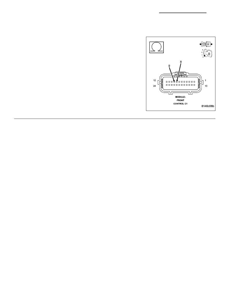
(D65) CAN C BUS (+) CIRCUIT SHORTED TO (D64) CAN C BUS (-) CIRCUIT
Measure the resistance between the (D65) CAN C Bus (+) circuit and
the (D64) CAN C Bus (-) circuit.
Is any resistance present?
Yes
>> Repair the (D65) CAN C Bus (+) circuit for a short to the
(D64) CAN C Bus (-) circuit.
Perform BODY VERIFICATION TEST - VER 1. (Refer to
BODY VERIFICATION TEST - VER 1).
No
>> Inspect the wiring and connectors for damage or shorted
circuits. If ok, replace and program the Front Control Mod-
ule in accordance with the service information.
Perform BODY VERIFICATION TEST - VER 1. (Refer to
BODY VERIFICATION TEST - VER 1).
8E - 16
ELECTRONIC CONTROL MODULES - ELECTRICAL DIAGNOSTICS
ND
U0021-CAN B BUS (+) CIRCUIT OPEN
ND
ELECTRONIC CONTROL MODULES - ELECTRICAL DIAGNOSTICS
8E - 17
U0021-CAN B BUS (+) CIRCUIT OPEN (CONTINUED)
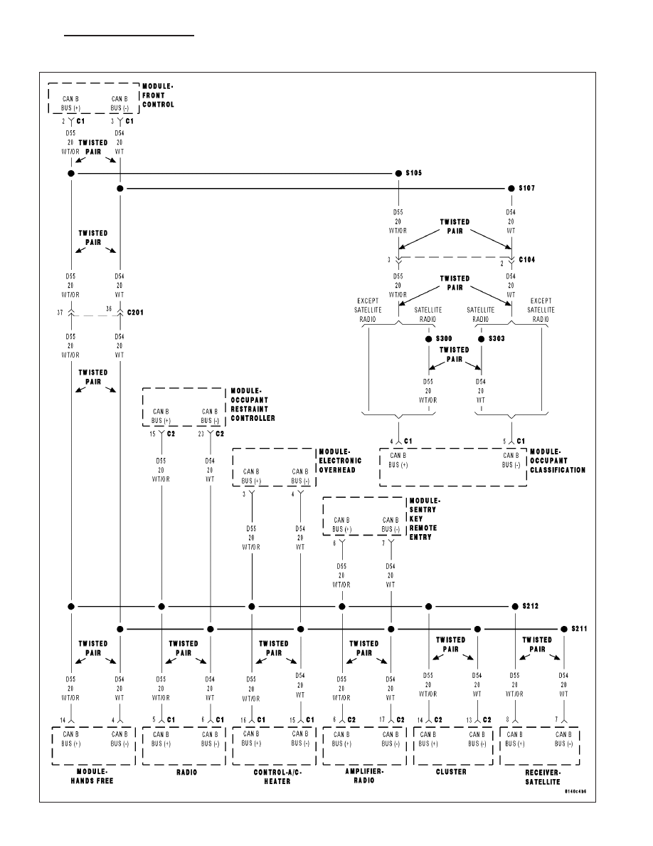
For a complete wiring diagram Refer to Section 8W.
•
When Monitored:
With the ignition on and battery voltage between 10 and 16 volts.
•
Set Condition:
The FCM detects the (D55) CAN B Bus (+) circuit is open.
Possible Causes
CAN B BUS TERMINAL PUSH OUT
SPREAD CAN B BUS TERMINAL
(D55) CAN B BUS (+) CIRCUIT OPEN
INTERNAL OPEN IN A CAN B BUS MODULE
Diagnostic Test
1.
TEST FOR INTERMITTENT CONDITION
Turn the ignition on.
With the scan tool, record and erase FCM DTC’s
Cycle the ignition from on to off 3 times.
Turn the ignition on.
With the scan tool, read active FCM DTC’s.
Does the scan tool display this DTC as active?
Yes
>> Go To 2
No
>> The conditions that caused this code to set are not present at this time. Using the wiring diagram/sche-
matic as a guide, inspect the wiring and connectors.
8E - 18
ELECTRONIC CONTROL MODULES - ELECTRICAL DIAGNOSTICS
ND
U0021-CAN B BUS (+) CIRCUIT OPEN (CONTINUED)
2.
ATTEMPT TO ISOLATE THE OPEN CONDITION
Turn the ignition on.
Verify that all CAN B Bus modules are communicating with the scan
tool.
NOTE: A red X will be next to the module that is not communi-
cating, indicating that the module is not active on the Bus net-
work. A green check indicates that the module is active on the
Bus network.
NOTE: If any module is not communicating, perform the appropri-
ate no response test procedure before proceeding.
Turn the ignition off.
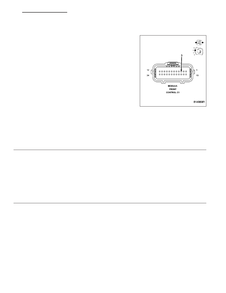
Gain access to the Front Control Module C1 harness connector, but
do not disconnect.
Using a fused jumper wire, connect one end to ground and with the
other end backprobe the CAN B Bus (-) circuit at the FCM C1 harness
connector.
Turn the ignition on.
With the scan tool monitor the network status screen and document all modules that display a red X.
Are there any red X’s displayed next to the modules?
Yes
>> Go To 3
No
>> Check backprobe connection to ground, make sure it is proper. The CAN B Bus open DTC may no
longer be active, it may be stored. Check all module connections
Perform BODY VERIFICATION TEST - VER 1. (Refer to BODY VERIFICATION TEST - VER 1).
3.
ATTEMPT TO ISOLATE THE OPEN CONDITION — MULTIPLE RED X’S
With the scan tool continue monitoring the network status screen.
Are there multiple red X’s displayed next to the modules?
Yes
>> The most likely cause of this condition is an open CAN B Bus (+) circuit between a common CAN B
Bus splice and the modules that display the red X next to them. Use the wiring diagrams will help you
determine where open condition exists.
Perform BODY VERIFICATION TEST - VER 1. (Refer to BODY VERIFICATION TEST - VER 1).
No
>> Go To 4
ND
ELECTRONIC CONTROL MODULES - ELECTRICAL DIAGNOSTICS
8E - 19
Нет комментариевНе стесняйтесь поделиться с нами вашим ценным мнением.
Текст