Dodge Dakota (ND). Manual — part 733
P0461-FUEL LEVEL SENSOR 1 PERFORMANCE (CONTINUED)
5.
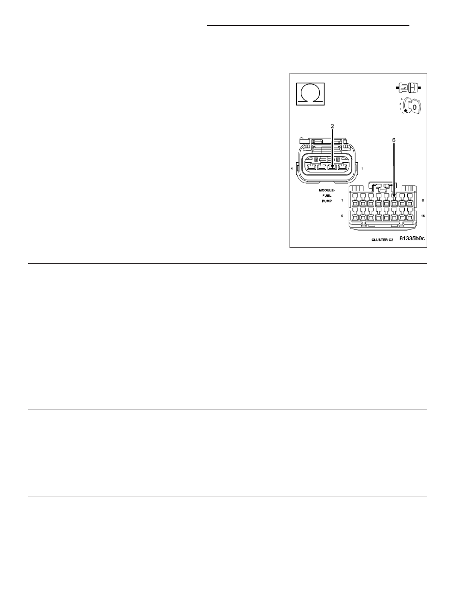
(N5) FUEL LEVEL SENSOR RETURN CIRCUIT OPEN
Measure the resistance of the (N5) Fuel Level Sensor Return circuit
from the Fuel Pump Module harness connector to the C2 Cluster har-
ness connector.
Is the resistance below 5.0 ohms?
Yes
>> Go To 6
No
>> Repair the open in the (N5) Fuel Level Sensor Return cir-
cuit.
Perform BODY VERIFICATION TEST-VER 1. (Refer to 8 -
ELECTRICAL/ELECTRONIC
CONTROL
MODULES/
FRONT CONTROL MODULE - DIAGNOSIS AND TEST-
ING)
6.
INTERNAL INSPECTION OF THE FUEL TANK
WARNING: The fuel system is under a constant pressure (even with the engine off). Before testing or ser-
vicing any fuel system hose, fitting or line, the fuel system pressure must be released. Failure to follow
these instructions can result in personal injury or death.
Remove the Fuel Tank per Service Information.
Remove the Fuel Pump Module.
Visually inspect the inside of the Fuel Tank for any obstructions or deformities.
Inspect the Fuel Pump Module Float arm for damage.
Were any problems found?
Yes
>> Repair or replace as necessary.
Perform POWERTRAIN VERIFICATION TEST. (Refer to 9 - ENGINE - STANDARD PROCEDURE)
No
>> Go To 7
7.
FUEL LEVEL SENSOR
If there are no possible causes remaining, view repair.
Repair
Replace the Fuel Level Sensor.
Perform BODY VERIFICATION TEST-VER 1. (Refer to 8 - ELECTRICAL/ELECTRONIC CONTROL
MODULES/FRONT CONTROL MODULE - DIAGNOSIS AND TESTING)
9 - 470
ENGINE ELECTRICAL DIAGNOSTICS
ND

P0462-FUEL LEVEL SENSOR 1 CIRCUIT LOW
ND
ENGINE ELECTRICAL DIAGNOSTICS
9 - 471
P0462-FUEL LEVEL SENSOR 1 CIRCUIT LOW (CONTINUED)
For the Engine circuit diagram (Refer to 9 - ENGINE - SCHEMATICS AND DIAGRAMS).
For a complete wiring diagram Refer to Section 8W.
•
When Monitored:
Ignition on and battery voltage above 10.4 volts.
•
Set Condition:
The fuel level sensor signal voltage goes below 0.4 of a volt for more than 90 seconds. One Trip Fault. Three
good trips to turn off the MIL.
Possible Causes
(N4) FUEL LEVEL SIGNAL CIRCUIT SHORTED TO GROUND
(N4) FUEL LEVEL SIGNAL CIRCUIT SHORTED TO THE (N5) FUEL LEVEL SENSOR RETURN CIRCUIT
FUEL LEVEL SENSOR
INSTRUMENT CLUSTER
Always perform the Pre-Diagnostic Troubleshooting procedure before proceeding. (Refer to 9 - ENGINE -
SCHEMATICS AND DIAGRAMS).
Diagnostic Test
1.
FUEL LEVEL SENSOR VOLTAGE BELOW 0.4 OF A VOLT
NOTE: Diagnose any CAN - B or CAN -C Communication DTCs before continuing.
Ignition on, engine not running.
With the scan tool, read the Fuel Level Sensor voltage.
Is the Fuel Level Sensor voltage below 0.4 of a volt?
Yes
>> Go To 2
No
>> Refer to the INTERMITTENT CONDITION Diagnostic Procedure.
Perform BODY VERIFICATION TEST-VER 1. (Refer to 8 - ELECTRICAL/ELECTRONIC CONTROL
MODULES/FRONT CONTROL MODULE - DIAGNOSIS AND TESTING)
2.
FUEL LEVEL SENSOR
Turn the ignition off.
Disconnect the Fuel Pump Module harness connector.
Ignition on, engine not running.
With the scan tool, read the Fuel Level Sensor voltage.
Did the Fuel Level Sensor voltage change from below 0.4 of a volt to above 4.0 volts?
Yes
>> Replace the Fuel Level Sensor.
Perform BODY VERIFICATION TEST-VER 1. (Refer to 8 - ELECTRICAL/ELECTRONIC CONTROL
MODULES/FRONT CONTROL MODULE - DIAGNOSIS AND TESTING)
No
>> Go To 3
9 - 472
ENGINE ELECTRICAL DIAGNOSTICS
ND
P0462-FUEL LEVEL SENSOR 1 CIRCUIT LOW (CONTINUED)
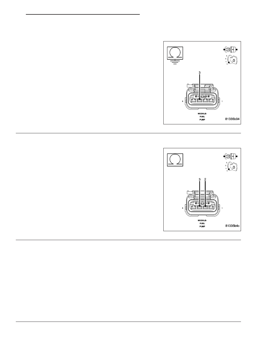
3.
(N4) FUEL LEVEL SIGNAL CIRCUIT SHORTED TO GROUND
Turn the ignition off.
Disconnect the C2 Cluster harness connector.
Measure the resistance between ground and the (N4) Fuel Level Sig-
nal circuit in the Fuel Pump Module harness connector.
Is the resistance below 100 ohms?
Yes
>> Repair the short to ground in the (N4) Fuel Level Signal
circuit.
Perform BODY VERIFICATION TEST-VER 1. (Refer to 8 -
ELECTRICAL/ELECTRONIC
CONTROL
MODULES/
FRONT CONTROL MODULE - DIAGNOSIS AND TEST-
ING)
No
>> Go To 4
4.
(N4) FUEL LEVEL SIGNAL CIRCUIT SHORTED TO THE (N5) FUEL LEVEL SENSOR RETURN CIRCUIT
Measure the resistance between the (N4) Fuel Level Signal circuit and
the (N5) Fuel Level Sensor Return circuit in the Fuel Pump Module
harness connector.
Is the resistance below 5.0 ohms?
Yes
>> Repair the short between the (N5) Fuel Level Sensor
Return circuit and the (N4) Fuel Level Signal circuit.
Perform BODY VERIFICATION TEST-VER 1. (Refer to 8 -
ELECTRICAL/ELECTRONIC
CONTROL
MODULES/
FRONT CONTROL MODULE - DIAGNOSIS AND TEST-
ING)
No
>> Go To 5
5.
INSTRUMENT CLUSTER
NOTE: Before continuing, check the Instrument Cluster harness connector terminals for corrosion, damage,
or terminal push out. Repair as necessary.
Using the schematics as a guide, inspect the wire harness and connectors. Pay particular attention to all Power and
Ground circuits.
Were there any problems found?
Yes
>> Repair as necessary.
Perform BODY VERIFICATION TEST-VER 1. (Refer to 8 - ELECTRICAL/ELECTRONIC CONTROL
MODULES/FRONT CONTROL MODULE - DIAGNOSIS AND TESTING)
No
>> Replace and program the Instrument Cluster per Service Information.
Perform BODY VERIFICATION TEST-VER 1. (Refer to 8 - ELECTRICAL/ELECTRONIC CONTROL
MODULES/FRONT CONTROL MODULE - DIAGNOSIS AND TESTING)
ND
ENGINE ELECTRICAL DIAGNOSTICS
9 - 473
Нет комментариевНе стесняйтесь поделиться с нами вашим ценным мнением.
Текст