Dodge Dakota (ND). Manual — part 881
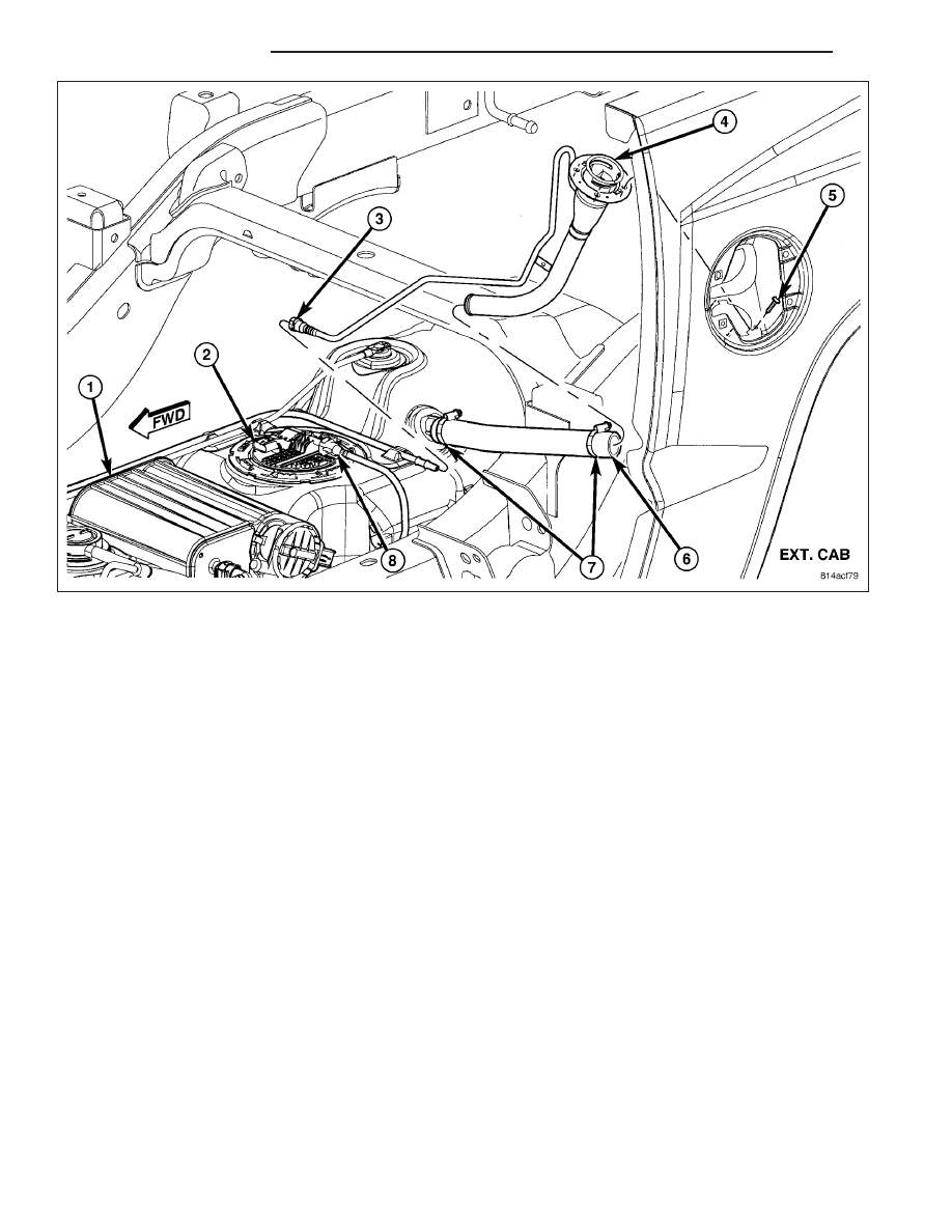
10. Connect vent line (3).
11. Connect rubber fill hose (6) to fuel tank fitting and tighten hose clamps (7).
12. The vapor/vacuum lines and hoses must be firmly connected. Also check the vapor/vacuum lines at the
NVLD pump, NVLD filter and EVAP canister purge solenoid for damage or leaks. If a leak is present, a
Diagnostic Trouble Code (DTC) may be set.
13. If equipped, install fuel tank skid plate.
14. Install plastic liner in front of left-rear tire/wheel.
15. Install left-rear tire/wheel.
16. Lower vehicle.
17. Fill fuel tank with fuel.
18. Start engine and check for fuel leaks near top of module.
14 - 22
FUEL DELIVERY
ND
FILTER-INLET
DESCRIPTION
Refer to Fuel Pump Module for information.
REGULATOR-FUEL PRESSURE
DESCRIPTION
Refer to Fuel Pump Module for information.
FILTER-FUEL
DESCRIPTION
Refer to Fuel Pump Module for information.
ND
FUEL DELIVERY
14 - 23
FUEL INJECTION
TABLE OF CONTENTS
page
page
PEDAL-ACCELERATOR
. . . . . . . . . . . . . . . . . . . . . . . . . . . . . 24
. . . . . . . . . . . . . . . . . . . . . . . . . 25
SENSOR-CRANKSHAFT POSITION
. . . . . . . . . . . . . . . . . . . . . . . . . 25
. . . . . . . . . . . . . . . . . . . . . . . . . . . 26
. . . . . . . . . . . . . . . . . . . . . . . . . . . . . 27
. . . . . . . . . . . . . . . . . . . . . . . . . 29
INJECTOR-FUEL
. . . . . . . . . . . . . . . . . . . . . . . . . 30
. . . . . . . . . . . . . . . . . . . . . . . . . . . . . 31
. . . . . . . . . . . . . . . . . . . . . . . . . 31
RELAY-FUEL PUMP
. . . . . . . . . . . . . . . . . . . . . . . . . 31
. . . . . . . . . . . . . . . . . . . . . . . . . . . 32
. . . . . . . . . . . . . . . . . . . . . . . . . . . . . 32
. . . . . . . . . . . . . . . . . . . . . . . . . 32
MOTOR-IDLE AIR CONTROL
. . . . . . . . . . . . . . . . . . . . . . . . . 32
. . . . . . . . . . . . . . . . . . . . . . . . . . . 33
. . . . . . . . . . . . . . . . . . . . . . . . . . . . . 34
. . . . . . . . . . . . . . . . . . . . . . . . . 35
SENSOR-INTAKE AIR TEMPERATURE
. . . . . . . . . . . . . . . . . . . . . . . . . 36
. . . . . . . . . . . . . . . . . . . . . . . . . . . 37
. . . . . . . . . . . . . . . . . . . . . . . . . . . . . 38
. . . . . . . . . . . . . . . . . . . . . . . . . 39
SENSOR-MAP
. . . . . . . . . . . . . . . . . . . . . . . . . 40
. . . . . . . . . . . . . . . . . . . . . . . . . . . 41
. . . . . . . . . . . . . . . . . . . . . . . . . . . . . 42
. . . . . . . . . . . . . . . . . . . . . . . . . 44
SENSOR-OXYGEN
. . . . . . . . . . . . . . . . . . . . . . . . . 45
. . . . . . . . . . . . . . . . . . . . . . . . . . . . . 45
. . . . . . . . . . . . . . . . . . . . . . . . . 46
THROTTLE BODY
. . . . . . . . . . . . . . . . . . . . . . . . . 46
. . . . . . . . . . . . . . . . . . . . . . . . . . . 46
. . . . . . . . . . . . . . . . . . . . . . . . . . . . . 46
. . . . . . . . . . . . . . . . . . . . . . . . . 48
CABLE-THROTTLE CONTROL
. . . . . . . . . . . . . . . . . . . . . . . . . . . . . 49
. . . . . . . . . . . . . . . . . . . . . . . . . 52
SENSOR-THROTTLE POSITION
. . . . . . . . . . . . . . . . . . . . . . . . . 55
. . . . . . . . . . . . . . . . . . . . . . . . . . . 56
. . . . . . . . . . . . . . . . . . . . . . . . . . . . . 56
. . . . . . . . . . . . . . . . . . . . . . . . . 57
PEDAL-ACCELERATOR
REMOVAL
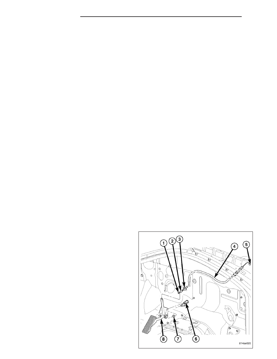
The accelerator pedal is serviced as a complete
assembly (8) including the bracket.
The accelerator cable (4) is connected to the upper
part of the accelerator pedal arm by a plastic retainer
(clip) (2). This plastic retainer snaps into the top of the
accelerator pedal arm.
1. From inside the vehicle, hold up accelerator pedal.
Remove plastic cable retainer (clip) (2) and throttle
cable core wire from upper end of accelerator
pedal arm. Plastic cable retainer (clip) snaps into
pedal arm.
2. Remove two accelerator pedal mounting bracket
nuts (7). Remove accelerator pedal assembly (8).
14 - 24
FUEL INJECTION
ND
INSTALLATION
The accelerator pedal is serviced as a complete
assembly (8) including the bracket.
The accelerator cable is connected to the upper part
of the accelerator pedal arm by a plastic retainer (clip)
(7). This plastic retainer snaps into the top of the
accelerator pedal arm.
1. Place accelerator pedal assembly (8) over two
mounting studs (6).
2. Install and tighten two mounting nuts (7). Refer to
Torque Specifications.
3. Slide throttle cable (1) into opening slot in top of
pedal arm.
4. Push plastic cable retainer (clip) (2) into accelerator
pedal arm opening until it snaps into place.
5. Before starting engine, operate accelerator pedal to
check for any binding.
SENSOR-CRANKSHAFT POSITION
DESCRIPTION
3.7L V-6
The Crankshaft Position (CKP) sensor (2) is mounted
into the right rear side of the cylinder block. It is posi-
tioned and bolted into a machined hole.
ND
FUEL INJECTION
14 - 25
Нет комментариевНе стесняйтесь поделиться с нами вашим ценным мнением.
Текст