Dodge Dakota (ND). Manual — part 1300
INSTALLATION
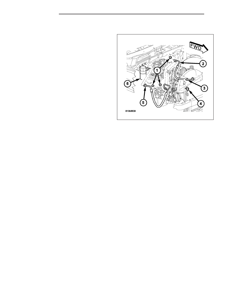
1. Position the A/C discharge line (2) into the engine
compartment.
2. Remove the tape or plugs from the opened dis-
charge line fittings and the condenser and com-
pressor ports
3. Lubricate new rubber O-ring seals with clean refrig-
erant oil and install them and new gaskets onto the
discharge line fittings. Use only the specified O-ring
as it is made of a special material for the R-134a
system. Use only refrigerant oil of the type recom-
mended for the A/C compressor in the vehicle.
4. Install the A/C discharge line to the A/C compres-
sor.
5. Install the nut (1) that secures the A/C discharge
line to the A/C compressor. Tighten the nut to 23
N·m (17 ft. lbs.).
6. Install the A/C discharge line to the A/C condenser
(4).
7. Install the nut (3) that secures the A/C discharge line to the A/C condenser. Tighten the nut to 20 N·m (15 ft.
lbs.).
8. Reconnect the negative battery cable.
9. Evacuate the refrigerant system (Refer to 24 - HEATING & AIR CONDITIONING/PLUMBING - STANDARD PRO-
CEDURE - REFRIGERANT SYSTEM EVACUATE).
10. Charge the refrigerant system (Refer to 24 - HEATING & AIR CONDITIONING/PLUMBING - STANDARD PRO-
CEDURE - REFRIGERANT SYSTEM CHARGE).
LINE-A/C LIQUID
DESCRIPTION
The A/C liquid line is the refrigerant line that carries refrigerant from the A/C condenser to the A/C evaporator. The
A/C liquid line uses a spring-lock type refrigerant line coupler to connect it to the A/C evaporator (Refer to 24 -
HEATING & AIR CONDITIONING/PLUMBING/REFRIGERANT LINE COUPLER - DESCRIPTION). The A/C liquid
line is made from light-weight aluminum and uses braze-less fittings.
The A/C liquid line includes the high-side service port, the fixed A/C orifice tube and a fitting for the A/C pressure
transducer. For more information refer to 24 - HEATING & AIR CONDITIONING/PLUMBING/SERVICE PORT
VALVE CORE - DESCRIPTION, 24 - HEATING & AIR CONDITIONING/PLUMBING/A/C ORIFICE TUBE -
DESCRIPTION and 24 - HEATING & AIR CONDITIONING/CONTROLS/TRANSDUCER-A/C PRESSURE -
DESCRIPTION.
CAUTION: Use only O-ring seals specified for the vehicle. Failure to use the correct O-ring seal will cause
the refrigerant system connections to leak.
The A/C liquid line has no serviceable parts except for the rubber O-ring seals and gasket, high-side service port
valve, cap and secondary retaining clip. The O-ring seals used on the connections are made from a special type of
rubber not affected by R-134a refrigerant. The O-ring seals and gasket must be replaced whenever the A/C liquid
line is removed and installed.
If the A/C liquid line is found to be leaking or is damaged, it must be replaced.
24 - 198
PLUMBING
ND
REMOVAL
WARNING: Refer to the applicable warnings and cautions for this system before performing the following
operation (Refer to 24 - HEATING & AIR CONDITIONING/PLUMBING - WARNINGS) and (Refer to 24 - HEAT-
ING & AIR CONDITIONING/PLUMBING - CAUTIONS). Failure to follow the warnings and cautions could result
in possible personal injury or death.
1. Recover the refrigerant from the refrigerant system
(Refer to 24 - HEATING & AIR CONDITIONING/
PLUMBING
-
STANDARD
PROCEDURE
-
REFRIGERANT SYSTEM RECOVERY).
2. Disconnect and isolate the negative battery cable.
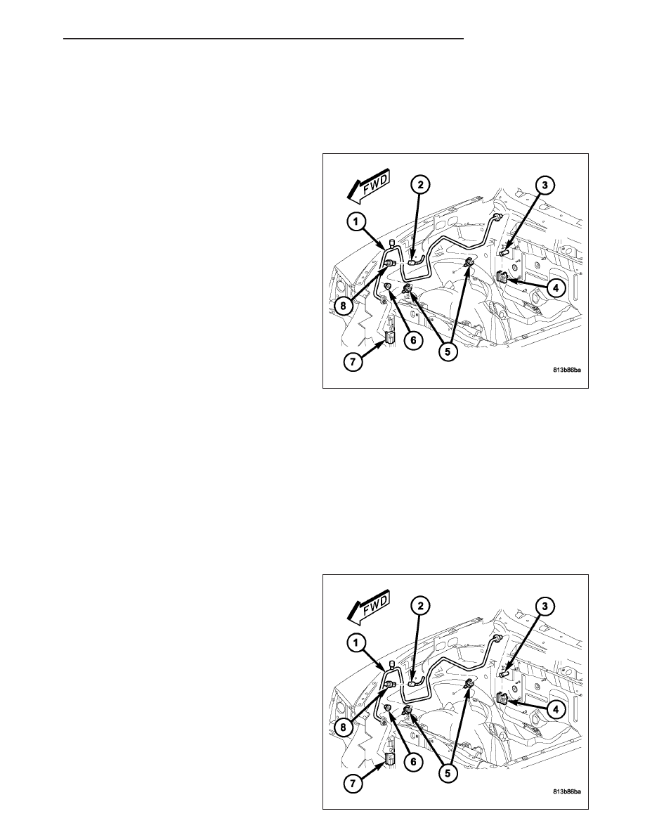
3. Disconnect the wire harness connector (2) from the
A/C pressure transducer (8).
4. Remove the air filter housing (Refer to 9 -
ENGINE/AIR
INTAKE
SYSTEM/AIR
FILTER
HOUSING - REMOVAL).
5. Remove the nut (6) that secures the A/C liquid line
(1) to the condenser outlet port (7).
6. Disconnect the A/C liquid line from the A/C con-
denser and remove and discard the O-ring seal
and gasket.
7. Disengage the A/C liquid line from the body retain-
ing clips (5).
8. Remove the secondary retaining clip (4) from the
spring-lock coupler that secures the A/C liquid line to evaporator inlet tube (3).
9. Using the proper A/C line disconnect tool, disconnect the A/C liquid line from the evaporator inlet tube and
remove and discard the O-ring seals (Refer to 24 - HEATING & AIR CONDITIONING/PLUMBING/COUPLER-
REFRIGERANT LINE - REMOVAL).
10. Install plugs in, or tape over the opened ends of the A/C liquid line and the condenser and evaporator ports.
11. Remove the A/C liquid line from the engine compartment.
12. If required , remove the A/C pressure transducer from the A/C liquid line (Refer to 24 - HEATING & AIR CON-
DITIONING/CONTROLS/TRANSDUCER-A/C PRESSURE - REMOVAL).
INSTALLATION
1. If removed, install the A/C pressure transducer (8)
onto the A/C liquid line (1).
2. Position the A/C liquid line into the engine compart-
ment.
3. Remove the tape or plugs from the opened ends of
the A/C liquid line and the condenser and evapora-
tor ports.
4. Lubricate new O-ring seals with clean refrigerant oil
and install them onto the liquid line spring-lock cou-
pler fitting. Use only the specified O-ring seals as
they are made of a special material for the R-134a
system. Use only refrigerant oil of the type recom-
mended for the A/C compressor in the vehicle.
5. Connect the A/C liquid line to the evaporator inlet
tube (3) (Refer to 24 - HEATING & AIR CONDI-
TIONING/PLUMBING/COUPLER-REFRIGERANT
LINE - INSTALLATION).
ND
PLUMBING
24 - 199
6. Install the secondary retaining clip (4) onto the spring-lock coupler that secures the A/C liquid line to the evap-
orator inlet tube.
7. Engage the A/C liquid line into the body retaining clips (5).
8. Lubricate a new O-ring seal with clean refrigerant oil and install it and a new gasket onto the liquid line fitting.
Use only the specified O-ring seal as it is made of a special material for the R-134a system. Use only refrigerant
oil of the type recommended for the A/C compressor in the vehicle.
9. Connect the A/C liquid line to the condenser outlet port (7).
10. Install the nut (6) that secures the A/C liquid line to the condenser outlet port. Tighten the nut to 20 N·m (15 ft.
lbs.).
11. Install the air filter housing (Refer to 9 - ENGINE/AIR INTAKE SYSTEM/AIR FILTER HOUSING - INSTALLA-
TION).
12. Connect the wire harness connector (2) to the A/C pressure transducer.
13. Reconnect the negative battery cable.
14. Evacuate the refrigerant system (Refer to 24 - HEATING & AIR CONDITIONING/PLUMBING - STANDARD
PROCEDURE - REFRIGERANT SYSTEM EVACUATE).
15. Charge the refrigerant system (Refer to 24 - HEATING & AIR CONDITIONING/PLUMBING - STANDARD PRO-
CEDURE - REFRIGERANT SYSTEM CHARGE).
LINE-A/C SUCTION
DESCRIPTION
The A/C suction line is the refrigerant line that carries refrigerant from the A/C accumulator to the A/C compressor.
CAUTION: Use only O-ring seals specified for the vehicle. Failure to use the correct O-ring seals will cause
the refrigerant system connections to leak.
The A/C suction line has no serviceable parts except for the rubber O-ring seals and gaskets. The O-ring seals used
on the connections are made from a special type of rubber not affected by R-134a refrigerant. The O-ring seals and
gaskets must be replaced whenever the A/C suction line is removed and installed.
If the A/C suction line is found to be leaking or is damaged, it must be replaced.
REMOVAL
WARNING: Refer to the applicable warnings and cautions for this system before performing the following
operation (Refer to 24 - HEATING & AIR CONDITIONING/PLUMBING - WARNINGS) and (Refer to 24 - HEAT-
ING & AIR CONDITIONING/PLUMBING - CAUTIONS). Failure to follow the warnings and cautions could result
in possible personal injury or death.
24 - 200
PLUMBING
ND
1. Recover the refrigerant from the refrigerant system
(Refer to 24 - HEATING & AIR CONDITIONING/
PLUMBING
-
STANDARD
PROCEDURE
-
REFRIGERANT SYSTEM RECOVERY).
2. Disconnect and isolate the negative battery cable.
3. Remove the resonator from the engine.
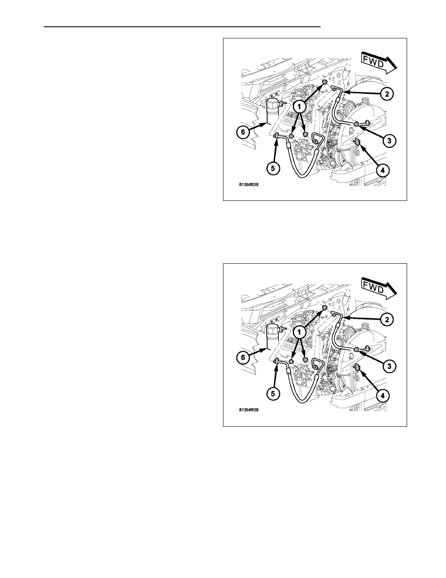
4. Remove the nut (1) that secures the A/C suction
line (5) to the A/C accumulator (6).
5. Disconnect the A/C suction line from the A/C accu-
mulator and remove and discard the O-ring seal
and gasket.
6. Remove the nut (1) that secures the A/C suction
line to the A/C compressor.
7. Disconnect the A/C suction line from the A/C com-
pressor and remove and discard the O-ring seal
and gasket.
8. Install plugs in, or tape over the suction line fittings
and the accumulator and compressor ports.
9. Remove the A/C suction line from the engine compartment.
INSTALLATION
1. Position the A/C suction line (5) into the engine
compartment.
2. Remove the tape or plugs from the opened suction
line fittings and the accumulator and compressor
ports.
3. Lubricate new rubber O-ring seals with clean refrig-
erant oil and install them and new gaskets onto the
suction line fittings. Use only the specified O-ring
as it is made of a special material for the R-134a
system. Use only refrigerant oil of the type recom-
mended for the A/C compressor in the vehicle.
4. Install the A/C suction line to the A/C compressor.
5. Install the nut (1) that secures the A/C suction line
to the A/C compressor. Tighten the nut to 23 N·m
(17 ft. lbs.).
6. Install the A/C suction line to the A/C accumulator
(6).
7. Install the nut (1) that secures the A/C suction line
to the A/C accumulator. Tighten the nut to 20 N·m (15 ft. lbs.).
8. Install the resonator onto the engine.
9. Reconnect the negative battery cable.
10. Evacuate the refrigerant system (Refer to 24 - HEATING & AIR CONDITIONING/PLUMBING - STANDARD
PROCEDURE - REFRIGERANT SYSTEM EVACUATE).
11. Charge the refrigerant system (Refer to 24 - HEATING & AIR CONDITIONING/PLUMBING - STANDARD PRO-
CEDURE - REFRIGERANT SYSTEM CHARGE).
ND
PLUMBING
24 - 201
Нет комментариевНе стесняйтесь поделиться с нами вашим ценным мнением.
Текст