Dodge Dakota (ND). Manual — part 1308
EXHAUST GAS RECIRCULATION
TABLE OF CONTENTS
page
page
VALVE-EGR
. . . . . . . . . . . . . . . . . . . . . . . . . 26
. . . . . . . . . . . . . . . . . . . . . . . . . . . 26
. . . . . . . . . . . . . . . . . . . . . . . . . . . . . 27
. . . . . . . . . . . . . . . . . . . . . . . . . 29
VALVE-EGR
DESCRIPTION
4.7L Engine
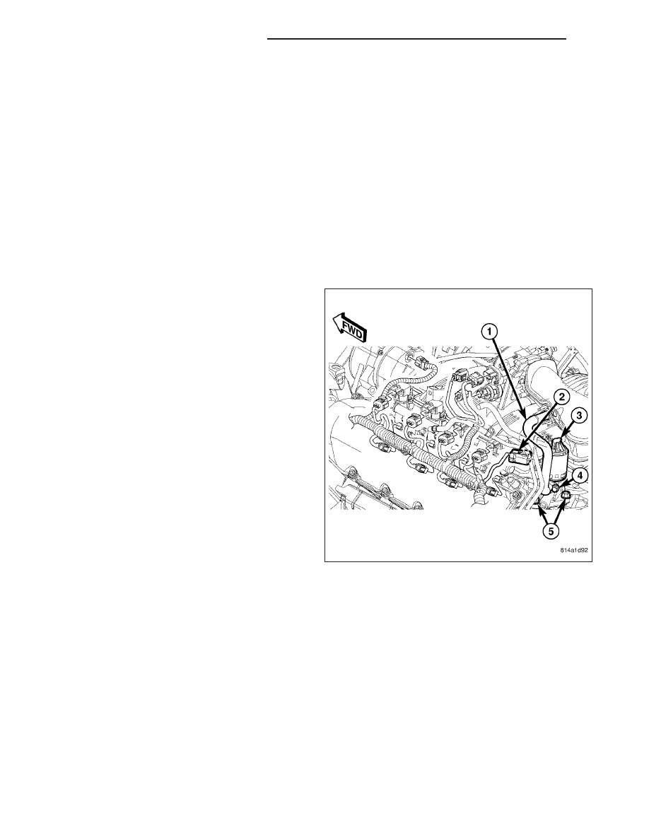
The electronic EGR valve and solenoid assembly (3)
is attached to the rear of the left cylinder head. An
exhaust gas routing tube (1) connects the EGR valve
to the intake manifold.
OPERATION
Exhaust gas recirculation flow is determined by the Powertrain Control Module (PCM) and is controlled by an elec-
tronic EGR valve assembly. For a given set of conditions, the PCM knows the ideal exhaust gas recirculation flow
to optimize NOx and fuel economy as a function of the pintle position. Pintle position is obtained from the position
sensor. The PCM adjusts the duty cycle of 128 Hz power supplied to the solenoid coil to obtain the correct position.
The electronic EGR valve assembly consists of a pintle, valve seat, and housing which contains and regulates
exhaust gas flow. An armature, return spring, and solenoid coil provide the operating force to regulate exhaust gas
flow by changing the pintle position. The solenoid coil assembly is wired in parallel with a diode that connects two
internal connectors.
25 - 26
EXHAUST GAS RECIRCULATION
ND
REMOVAL
4.7L Engine
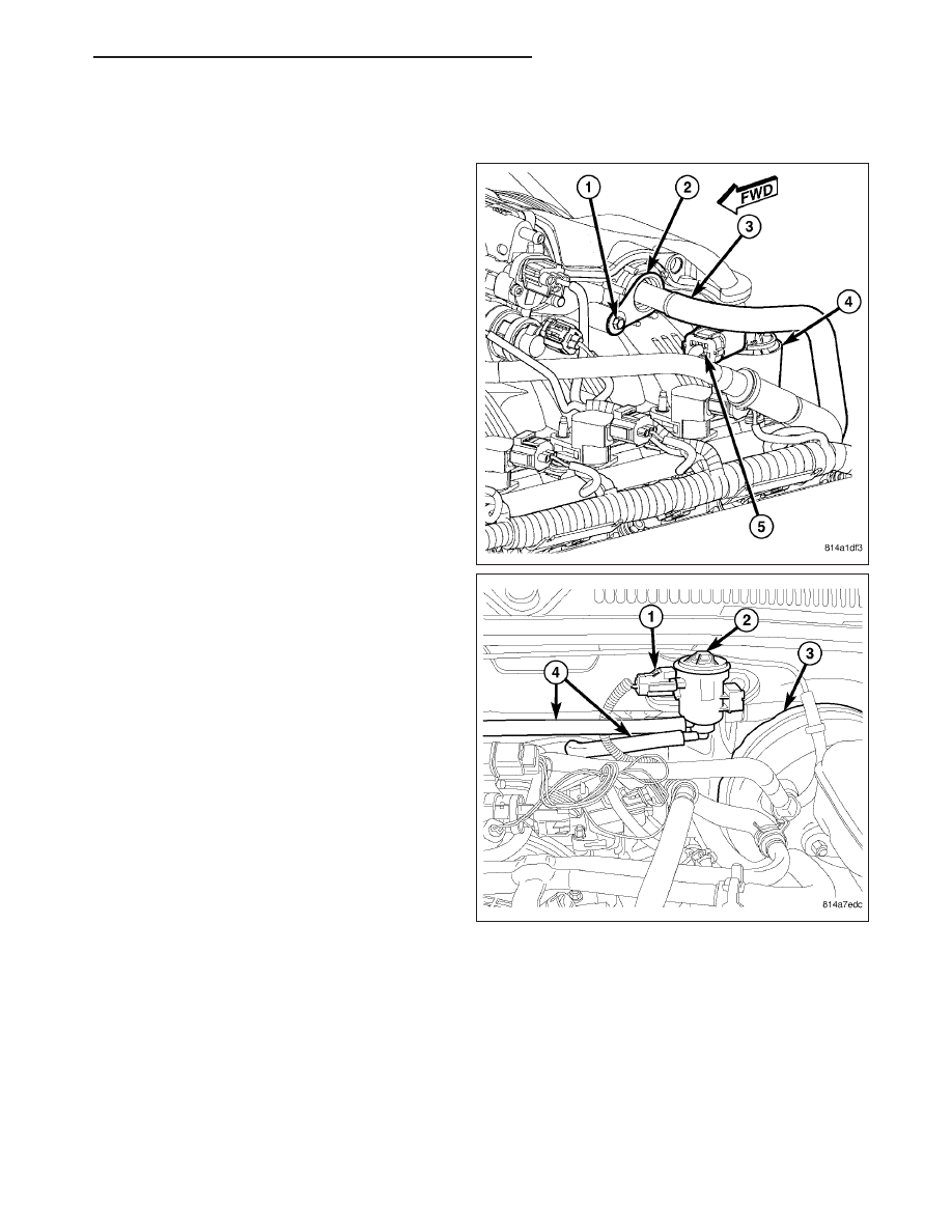
The electronic EGR valve and solenoid assembly (4)
is attached to the rear of the left cylinder head. An
exhaust gas routing tube (3) connects the EGR valve
to the intake manifold.
1. Remove EVAP solenoid (2). Refer to Solenoid -
EVAP/PURGE
Removal
and
Installation
for
procedures.
ND
EXHAUST GAS RECIRCULATION
25 - 27
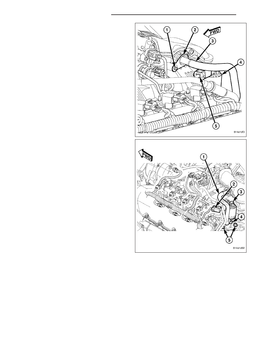
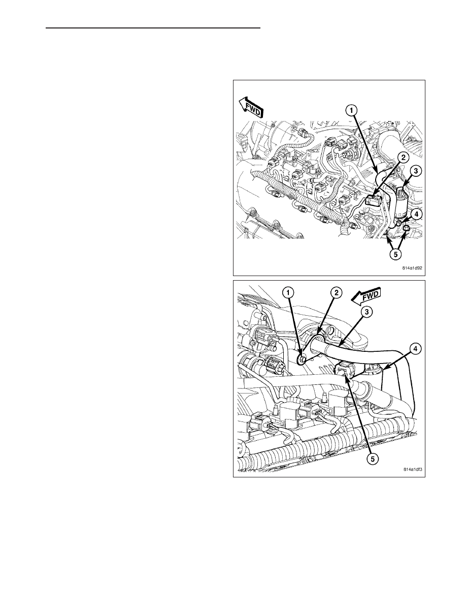
2. Remove electrical connector (5) at top of EGR
valve solenoid.
3. Remove tube mounting bolt (1) at intake manifold.
4. Remove two bolts (4) connecting EGR tube (1) to
valve assembly.
5. Remove gasket located between EGR tube flange
and EGR valve assembly.
6. Remove two EGR valve mounting bolts (5).
7. Separate valve assembly (3) from engine.
8. Remove and discard metal gasket located between
cylinder head and valve assembly.
25 - 28
EXHAUST GAS RECIRCULATION
ND
INSTALLATION
4.7L Engine
1. Clean area at rear of left cylinder head where it
joins base of EGR valve.
2. Clean EGR tube where it joins EGR valve.
3. Position new gasket between EGR valve and cylin-
der head.
4. Position EGR valve to cylinder head. Install and
tighten two bolts (5). Refer to Torque Specifica-
tions.
5. Position new gasket between EGR tube flange and
EGR valve assembly.
6. Position EGR tube (1) to side of EGR valve and
into intake manifold. Install two bolts (4) finger tight
(temporarily).
7. Install EGR tube flange bolt (1) at intake manifold.
Tighten bolt. Refer to Torque Specifications.
8. Connect electrical connector (5) to top of EGR
valve solenoid (2).
ND
EXHAUST GAS RECIRCULATION
25 - 29
Нет комментариевНе стесняйтесь поделиться с нами вашим ценным мнением.
Текст