Dodge Dakota (ND). Manual — part 1118
C140C- TRANSFER CASE MOTOR CONTROL CIRCUIT HIGH (CONTINUED)
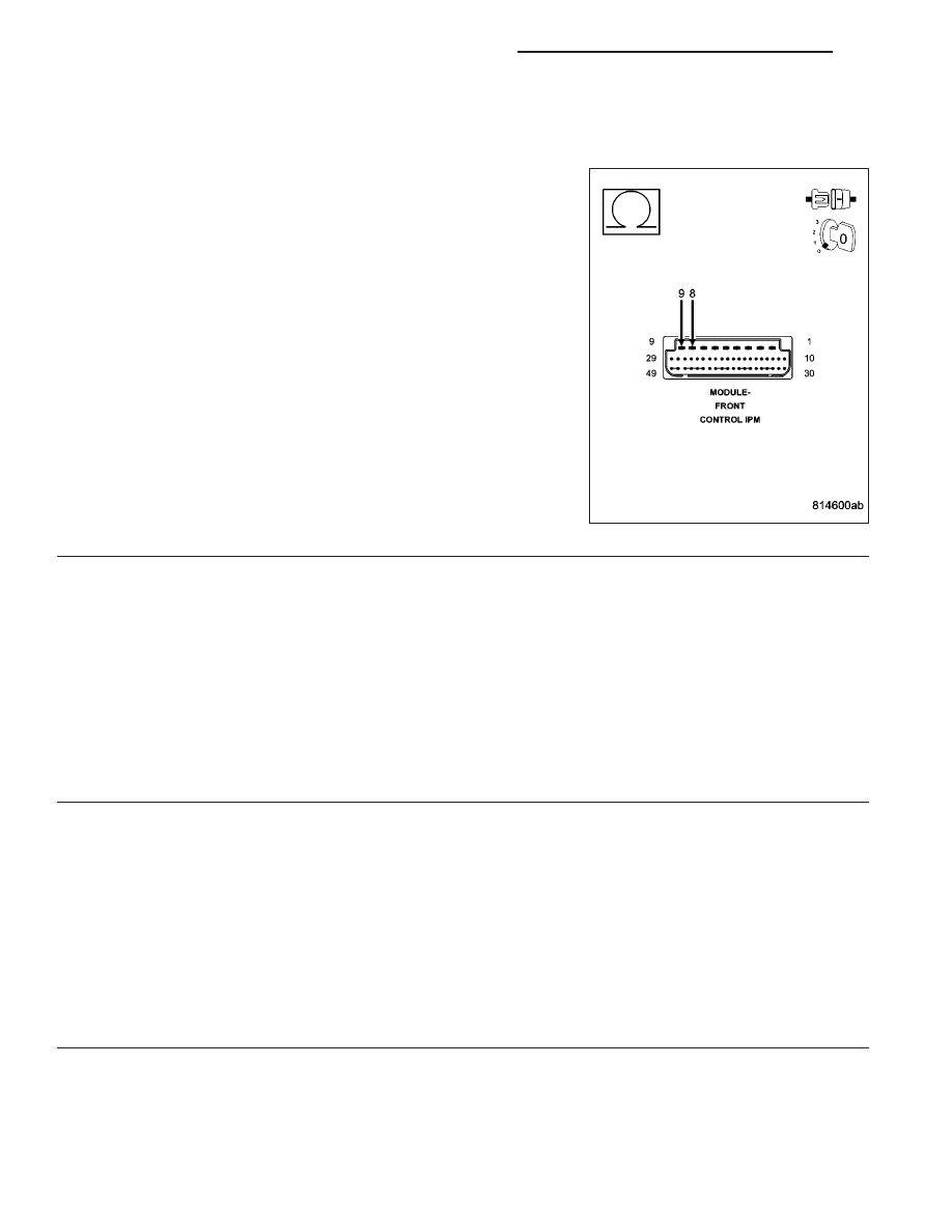
10.
(T315) SHIFT MOTOR CONTROL A CIRCUIT SHORTED TO (T316) SHIFT MOTOR CONTROL B CIRCUIT
(IPM)
Disconnect the Integrated Power Module C5 harness connector.
Measure the resistance between (T315) Shift Motor Control A circuit
and the (T316) Shift Motor Control B circuit at the Shift Motor/Mode
Sensor Assembly harness connector.
Is the resistance below 5.0 ohms?
Yes
>> Repair the (T315) Shift Motor Control A circuit for a short
to the (T316) Shift Motor Control B circuit.
Perform the TRANSFER CASE VERIFICATION TEST-
VER 1. (Refer to 8 - ELECTRICAL/ELECTRONIC CON-
TROL MODULES/TRANSFER CASE CONTROL MODULE
- DIAGNOSIS AND TESTING)
No
>> Go to 12
11.
SHIFT MOTOR/MODE SENSOR ASSEMBLY
Using the wiring diagram/schematic as a guide, inspect all wiring and connectors that pertain to this circuit.
Were any problems found?
Yes
>> Repair as necessary.
Perform the TRANSFER CASE VERIFICATION TEST-VER 1. (Refer to 8 - ELECTRICAL/ELECTRONIC
CONTROL MODULES/TRANSFER CASE CONTROL MODULE - DIAGNOSIS AND TESTING)
No
>> Replace the Shift Motor/Mode Sensor assembly in accordance with the Service Information.
Perform the TRANSFER CASE VERIFICATION TEST-VER 1. (Refer to 8 - ELECTRICAL/ELECTRONIC
CONTROL MODULES/TRANSFER CASE CONTROL MODULE - DIAGNOSIS AND TESTING)
12.
INTEGRATED POWER MODULE
Using the wiring diagram/schematic as a guide, inspect all wiring and connectors that pertain to this circuit.
Were any problems found?
Yes
>> Repair as necessary.
Perform the TRANSFER CASE VERIFICATION TEST-VER 1. (Refer to 8 - ELECTRICAL/ELECTRONIC
CONTROL MODULES/TRANSFER CASE CONTROL MODULE - DIAGNOSIS AND TESTING)
No
>> Replace the Integrated Power Module in accordance with the Service Information.
Perform the TRANSFER CASE VERIFICATION TEST-VER 1. (Refer to 8 - ELECTRICAL/ELECTRONIC
CONTROL MODULES/TRANSFER CASE CONTROL MODULE - DIAGNOSIS AND TESTING)
21 - 864
TRANSFER CASE - ELECTRICAL DIAGNOSTICS
ND
C140C- TRANSFER CASE MOTOR CONTROL CIRCUIT HIGH (CONTINUED)
13.
FRONT CONTROL MODULE
Using the wiring diagram/schematic as a guide, inspect all wiring and connectors that pertain to this circuit.
Were any problems found?
Yes
>> Repair as necessary.
Perform the TRANSFER CASE VERIFICATION TEST-VER 1. (Refer to 8 - ELECTRICAL/ELECTRONIC
CONTROL MODULES/TRANSFER CASE CONTROL MODULE - DIAGNOSIS AND TESTING)
No
>> Replace the Front Control Module in accordance with the Service Information.
Perform the TRANSFER CASE VERIFICATION TEST-VER 1. (Refer to 8 - ELECTRICAL/ELECTRONIC
CONTROL MODULES/TRANSFER CASE CONTROL MODULE - DIAGNOSIS AND TESTING)
14.
INTERMITTENT WIRING AND CONNECTORS
The conditions necessary to set this DTC are not present at this time.
Using the wiring diagram/schematic as a guide, inspect the wiring and connectors.
While monitoring the scan tool data relative to this circuit, wiggle test the wiring and connectors.
Look for the data to change or for the DTC to reset during the wiggle test.
Were any problems found?
Yes
>> Repair as necessary.
Perform the TRANSFER CASE VERIFICATION TEST-VER 1. (Refer to 8 - ELECTRICAL/ELECTRONIC
CONTROL MODULES/TRANSFER CASE CONTROL MODULE - DIAGNOSIS AND TESTING)
No
>> Test complete.
ND
TRANSFER CASE - ELECTRICAL DIAGNOSTICS
21 - 865
C230A- NEUTRAL INDICATOR CONTROL CIRCUIT LOW
21 - 866
TRANSFER CASE - ELECTRICAL DIAGNOSTICS
ND
C230A- NEUTRAL INDICATOR CONTROL CIRCUIT LOW (CONTINUED)
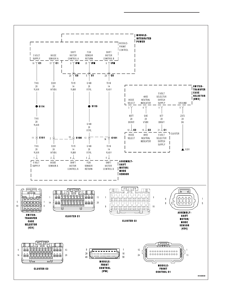
For a complete wiring diagram Refer to Section 8W
•
When Monitored:
With the ignition on.
•
Set Condition:
The Cluster detects low voltage on the Neutral Indicator Control Circuit.
Possible Causes
INTERMITTENT CONDITION
(G95) 4WD NEUTRAL INDICATOR CIRCUIT OPEN
(G95) 4WD NEUTRAL INDICATOR CIRCUIT SHORTED TO GROUND
TRANSFER CASE SELECTOR SWIITCH
INSTRUMENT CLUSTER
Diagnostic Test
1.
DTC IS ACTIVE
Ignition on.
With the scan tool, Clear DTCs.
Shift the Transfer Case into neutral for 30 seconds in accordance with the Service Information.
With the scan tool, select View DTCs.
Does this DTC reset?
Yes
>> Go to 2
No
>> Go to 7
2.
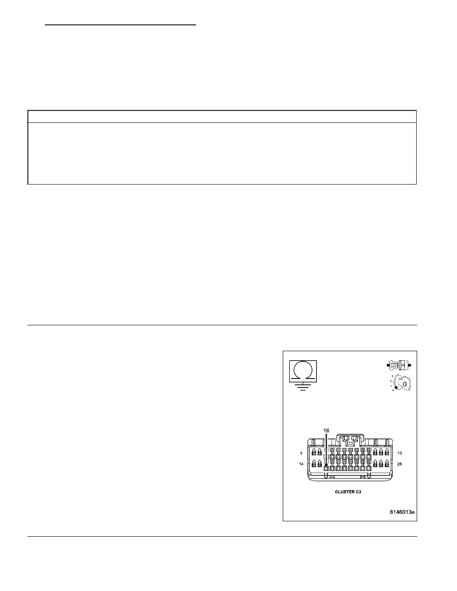
(G95) 4WD NEUTRAL INDICATOR CIRCUIT RESISTANCE TO GROUND
Turn the ignition off.
Disconnect the Instrument Cluster C3 connector.
Measure the resistance between ground and the (G95) 4WD Neutral
Indicator circuit.
Is the resistance below 5.0 ohms?
Yes
>> Go to 3
No
>> Go to 4
ND
TRANSFER CASE - ELECTRICAL DIAGNOSTICS
21 - 867
Нет комментариевНе стесняйтесь поделиться с нами вашим ценным мнением.
Текст