Dodge Dakota (ND). Manual — part 528
U0019–CAN B BUS (CONTINUED)
For a complete wiring diagram Refer to Section 8W.
•
When Monitored:
Continuously
•
Set Condition:
Whenever the CAN B Bus (+) or CAN B Bus (-) circuit is open, shorted to voltage or shorted to ground.
Possible Causes
CAN B BUS DTC’s IN FRONT CONTROL MODULE
(D55) CAN B BUS (+) CIRCUIT OPEN
(D54) CAN B BUS (-) CIRCUIT OPEN
HANDS FREE MODULE
Diagnostic Test
1.
CHECK FOR ACTIVE DTCS
With the scan tool, read the active DTC’s.
Cycle the ignition switch from off to on at least 5 times, leaving the ignition on for a minimum of 90 seconds per
cycle.
With the scan tool, read the active DTC’s.
Does the scan tool display this DTC as active?
Yes
>> Go To 2
No
>> If the DTC is stored, check for an intermittent condition. Visually inspect the related wiring harness con-
nectors. Look for broken, bent, pushed out, or corroded terminals.
2.
CHECK FRONT CONTROL MODULE DTC’s
With the scan tool, read Front Control Module active DTC’s
Does the scan tool display any CAN B BUS DTC’s – ACTIVE?
Yes
>> (Refer to 8 - ELECTRICAL/ELECTRONIC CONTROL MODULES - DIAGNOSIS AND TESTING) and
perform the appropriate DTC.
No
>> Go To 3
8T - 52
NAVIGATION/TELECOMMUNICATION - ELECTRICAL DIAGNOSTICS
ND
U0019–CAN B BUS (CONTINUED)
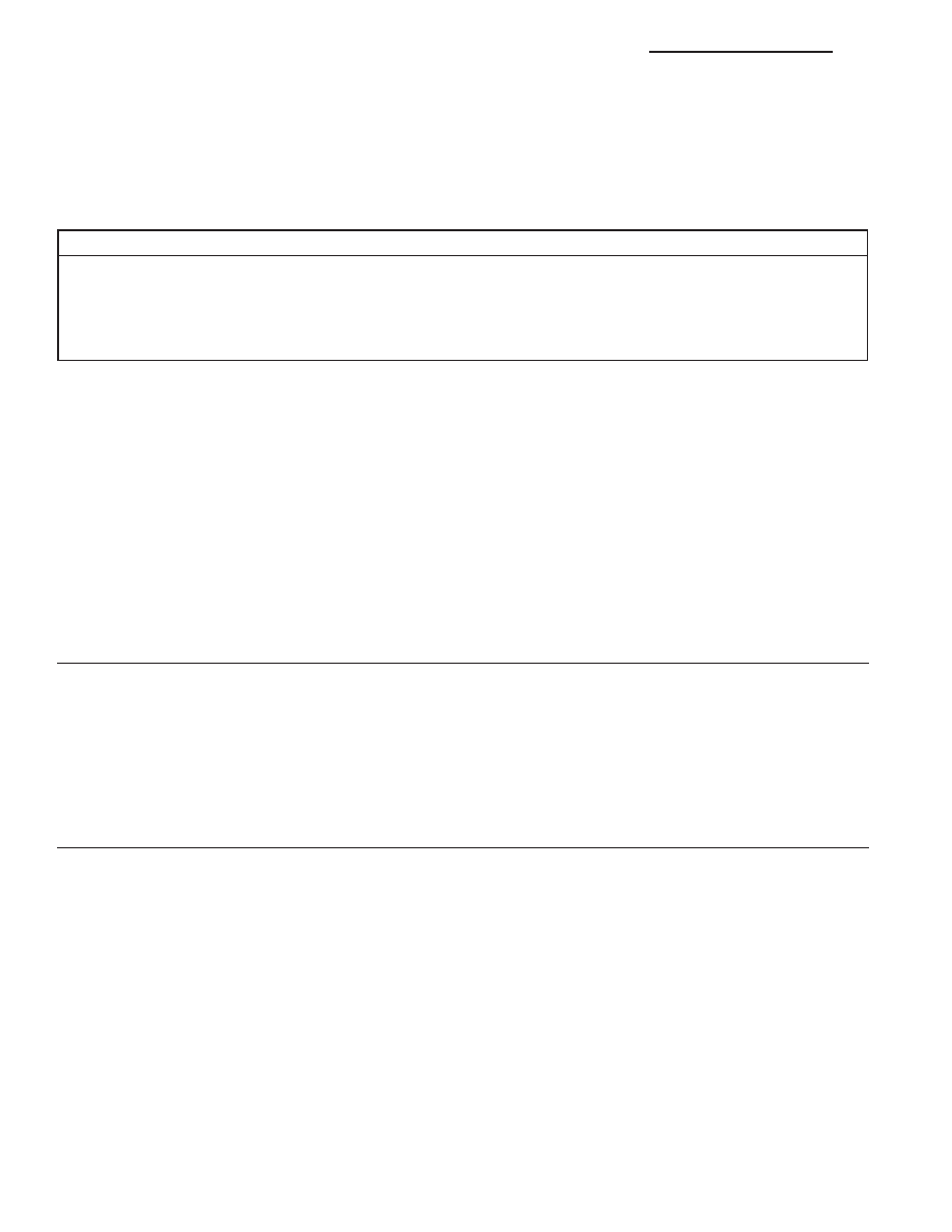
3.
(D55) CAN B BUS (+) CIRCUIT OPEN
Turn the ignition off.
Disconnect the negative battery cable.
Disconnect the Hands Free Module connector.
Disconnect the Front Control Module C1 connector.
Measure the resistance of the (D55) CAN B Bus (+) circuit between
the Front Control Module C1 connector and the Hands Free Module
connector.
Is the resistance below 2.0 ohms?
Yes
>> Go To 4
No
>> Repair the (D55) CAN B Bus (+) circuit for an open.
Perform BODY VERIFICATION TEST - VER 1. (Refer to
BODY VERIFICATION TEST - VER 1).
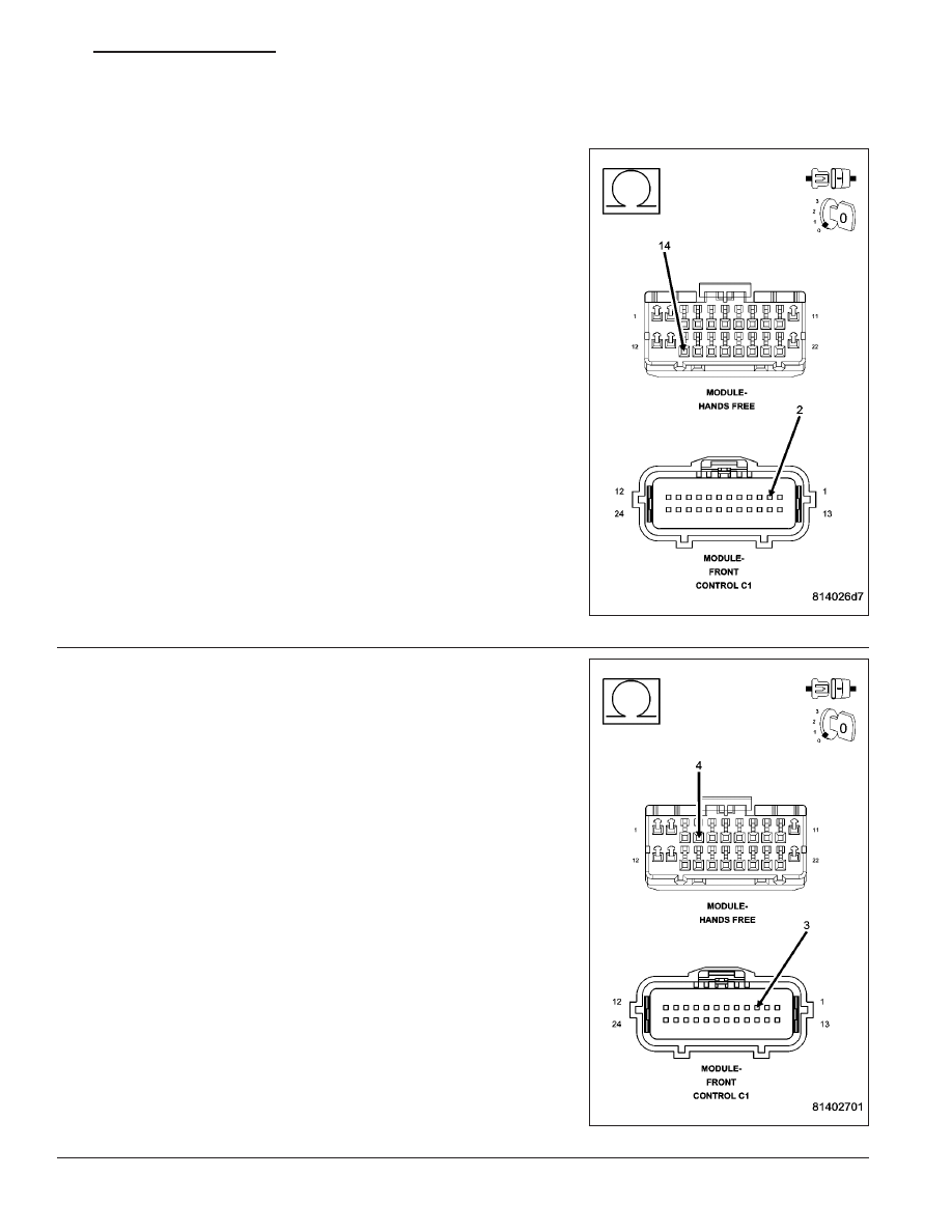
4.
(D54) CAN B BUS (–) CIRCUIT OPEN
Measure the resistance of the (D54) CAN B Bus (–) circuit between
the Front Control Module C1 connector and the Hands Free Module
connector.
Is the resistance below 2.0 ohms?
Yes
>> Replace and program the Hands Free Module in accor-
dance with the service information.
Perform BODY VERIFICATION TEST - VER 1. (Refer to
BODY VERIFICATION TEST - VER 1).
No
>> Repair the (D54) CAN B Bus (–) circuit for an open.
Perform BODY VERIFICATION TEST - VER 1. (Refer to
BODY VERIFICATION TEST - VER 1).
ND
NAVIGATION/TELECOMMUNICATION - ELECTRICAL DIAGNOSTICS
8T - 53
U0141–LOST COMMUNICATION WITH FRONT CONTROL MODULE
For a complete wiring diagram Refer to Section 8W.
(Refer to 8 - ELECTRICAL/ELECTRONIC CONTROL MODULES - DIAGNOSIS AND TESTING) for the diagnostic
test procedure.
U0151-LOST COMMUNICATION WITH OCCUPANT RESTRAINT CONTROLLER
For a complete wiring diagram Refer to Section 8W.
(Refer to 8 - ELECTRICAL/ELECTRONIC CONTROL MODULES - DIAGNOSIS AND TESTING) for the diagnostic
test procedure.
U0154-LOST COMMUNICATION WITH OCCUPANT CLASSIFICATION MODULE
For a complete wiring diagram Refer to Section 8W.
(Refer to 8 - ELECTRICAL/ELECTRONIC CONTROL MODULES - DIAGNOSIS AND TESTING) for the diagnostic
test procedure.
U0155-LOST COMMUNICATION WITH CLUSTER/CCN
For a complete wiring diagram Refer to Section 8W.
(Refer to 8 - ELECTRICAL/ELECTRONIC CONTROL MODULES - DIAGNOSIS AND TESTING) for the diagnostic
test procedure.
U0156-LOST COMMUNICATION WITH EOM
For a complete wiring diagram Refer to Section 8W.
(Refer to 8 - ELECTRICAL/ELECTRONIC CONTROL MODULES - DIAGNOSIS AND TESTING) for the diagnostic
test procedure.
U0164-LOST COMMUNICATION WITH HVAC CONTROL MODULE
For a complete wiring diagram Refer to Section 8W.
(Refer to 8 - ELECTRICAL/ELECTRONIC CONTROL MODULES - DIAGNOSIS AND TESTING) for the diagnostic
test procedure.
U0168-LOST COMMUNICATION WITH VEHICLE SECURITY CONTROL MODULE
(SKREEM/WCM)
For a complete wiring diagram Refer to Section 8W.
(Refer to 8 - ELECTRICAL/ELECTRONIC CONTROL MODULES - DIAGNOSIS AND TESTING) for the diagnostic
test procedure.
U0184-LOST COMMUNICATION WITH RADIO
For a complete wiring diagram Refer to Section 8W.
(Refer to 8 - ELECTRICAL/ELECTRONIC CONTROL MODULES - DIAGNOSIS AND TESTING) for the diagnostic
test procedure.
8T - 54
NAVIGATION/TELECOMMUNICATION - ELECTRICAL DIAGNOSTICS
ND
U0186-LOST COMMUNICATION WITH AUDIO AMPLIFIER
For a complete wiring diagram Refer to Section 8W.
(Refer to 8 - ELECTRICAL/ELECTRONIC CONTROL MODULES - DIAGNOSIS AND TESTING) for the diagnostic
test procedure.
U0195-LOST COMMUNICATION WITH SDARS
For a complete wiring diagram Refer to Section 8W.
(Refer to 8 - ELECTRICAL/ELECTRONIC CONTROL MODULES - DIAGNOSIS AND TESTING) for the diagnostic
test procedure.
ND
NAVIGATION/TELECOMMUNICATION - ELECTRICAL DIAGNOSTICS
8T - 55
Нет комментариевНе стесняйтесь поделиться с нами вашим ценным мнением.
Текст