Dodge Dakota (ND). Manual — part 984
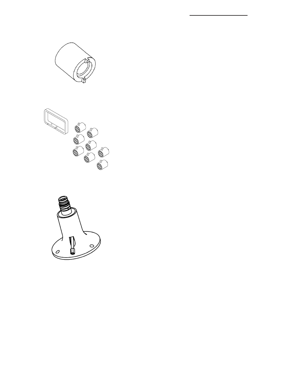
Tool, Staking - 6639
End Play Set - 8266
Fixture, Pressure - 8391
21 - 328
AUTOMATIC TRANSMISSION 42RLE - SERVICE INFORMATION
ND

ACCUMULATOR
DESCRIPTION
The 42RLE underdrive, overdrive, low/reverse, and
2/4 clutch hydraulic circuits each contain an accumu-
lator. An accumulator typically consists of a piston,
return spring(s), and a cover or plug. The overdrive (1)
and underdrive (2) accumulators are located within the
transmission case, and are retained by the valve body.
The low reverse (1) accumulator is also located within
the transmission case, but the assembly is retained by
a cover and a snap-ring.
ND
AUTOMATIC TRANSMISSION 42RLE - SERVICE INFORMATION
21 - 329
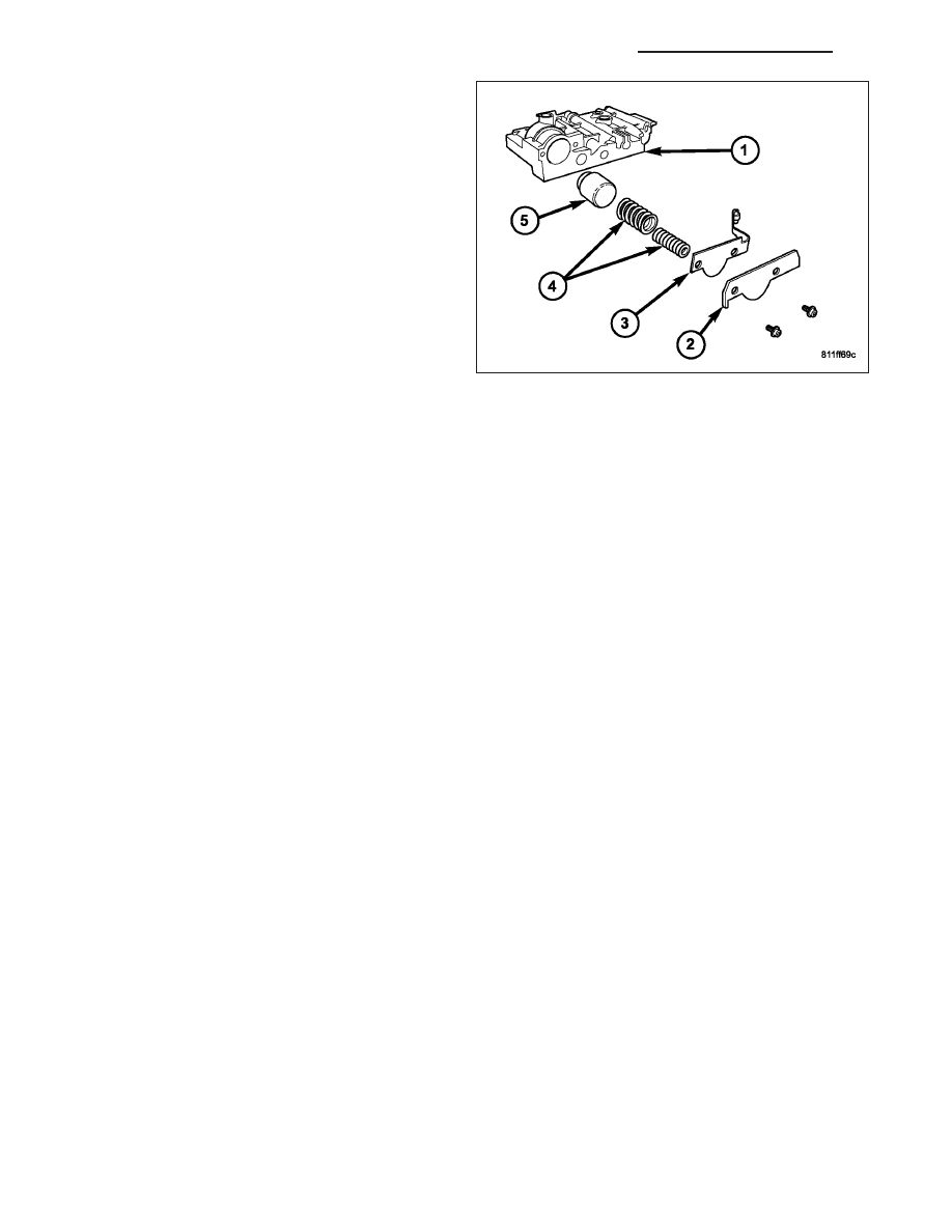
The 2/4 accumulator (5) is located in the valve body. It
is retained by a cover and retaining screws.
OPERATION
The function of an accumulator is to cushion the application of a frictional clutch element. When pressurized fluid is
applied to a clutch circuit, the application force is dampened by fluid collecting in the respective accumulator cham-
ber against the piston and springs. The intended result is a smooth, firm clutch application.
SEAL-ADAPTER HOUSING
REMOVAL
1. Remove the transfer case (Refer to 21 - TRANSMISSION/TRANSFER CASE - REMOVAL).
2. Using a screw mounted in a slide hammer, remove the adapter housing seal.
INSTALLATION
1. Install a new adapter housing seal with Tool Handle C-4171 and Installer C-3860-A.
2. Install the transfer case (Refer to 21 - TRANSMISSION/TRANSFER CASE - INSTALLATION).
BEARINGS
ADJUSTMENTS
BEARING ADJUSTMENT PROCEDURES
Take extreme care when removing and installing bearing cups and cones. Use only an arbor press for installa-
tion, as a hammer may not properly align the bearing cup or cone. Burrs or nicks on the bearing seat will give a
false end play reading, while gauging for proper shims. Improperly seated bearing cup and cones are subject to
low-mileage failure.
Bearing cups and cones should be replaced if they show signs of pitting or heat distress.
If distress is seen on either the cup or bearing rollers, both cup and cone must be replaced.
NOTE: Bearing drag torque specifications must be maintained to avoid premature bearing failures.
Used (original) bearing may lose up to 50 percent of the original drag torque after break-in.
NOTE: All bearing adjustments must be made with no other component interference or gear inter-mesh.
Oil all bearings before checking turning torque.
21 - 330
AUTOMATIC TRANSMISSION 42RLE - SERVICE INFORMATION
ND
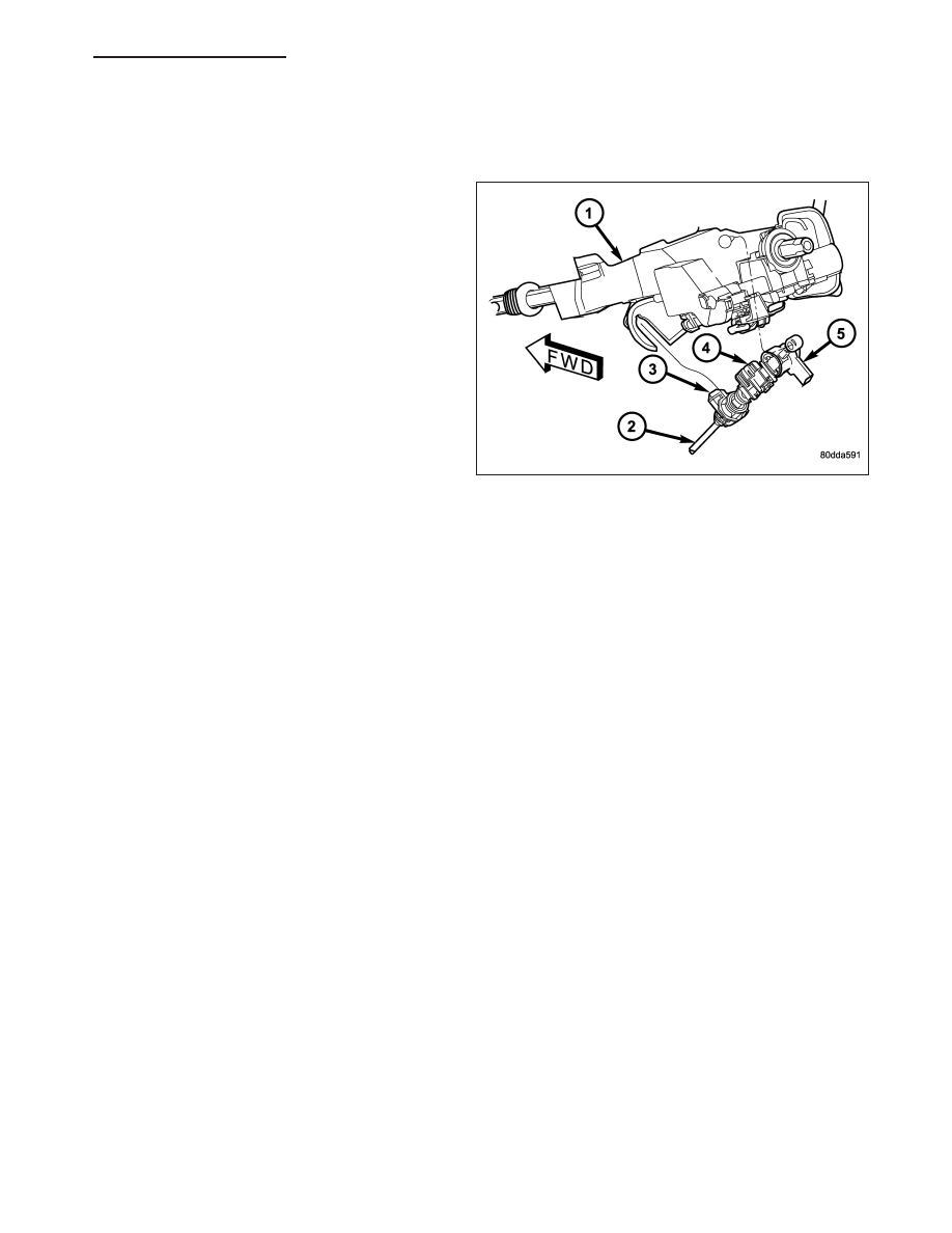
MECHANISM-BRAKE TRANSMISSION SHIFT INTERLOCK
DESCRIPTION
The Brake Transmission Shifter Interlock (BTSI), is a
solenoid operated system. It consists of a solenoid
permanently mounted on the gearshift cable.
OPERATION
The system locks the shifter into the PARK position. The interlock system is engaged whenever the ignition switch
is in the LOCK or ACCESSORY position. An additional electrically activated feature will prevent shifting out of the
PARK position unless the brake pedal is depressed approximately one-half an inch. A magnetic holding device in
line with the park lock cable is energized when the ignition is in the RUN position. When the key is in the RUN
position and the brake pedal is depressed, the shifter is unlocked and will move into any position. The interlock
system also prevents the ignition switch from being turned to the LOCK or ACCESSORY position, unless the shifter
is fully locked into the PARK position.
DIAGNOSIS AND TESTING - BRAKE TRANSMISSION SHIFT INTERLOCK
1. Verify that the key can only be removed in the PARK position.
2. When the shift lever is in PARK And the shift handle pushbutton is in the “OUT” position, the ignition key cylinder
should rotate freely from OFF to LOCK. When the shifter is in any other gear or neutral position, the ignition key
cylinder should not rotate to the LOCK position.
3. Shifting out of PARK should not be possible when the ignition key cylinder is in the OFF position.
4. Shifting out of PARK should not be possible while applying normal pushbutton force and ignition key cylinder is
in the RUN or START positions unless the foot brake pedal is depressed approximately 1/2 inch (12mm).
5. Shifting out of PARK should not be possible when the ignition key cylinder is in the ACCESSORY or LOCK
positions.
6. Shifting between any gears, NEUTRAL or into PARK may be done without depressing foot brake pedal with
ignition switch in RUN or START positions.
ADJUSTMENTS - BRAKE TRANSMISSION SHIFT INTERLOCK
Correct cable adjustment is important to proper interlock operation. The gearshift cable must be correctly adjusted
in order to shift out of PARK.
ND
AUTOMATIC TRANSMISSION 42RLE - SERVICE INFORMATION
21 - 331
Нет комментариевНе стесняйтесь поделиться с нами вашим ценным мнением.
Текст