Dodge Dakota (ND). Manual — part 331
INSTALLATION
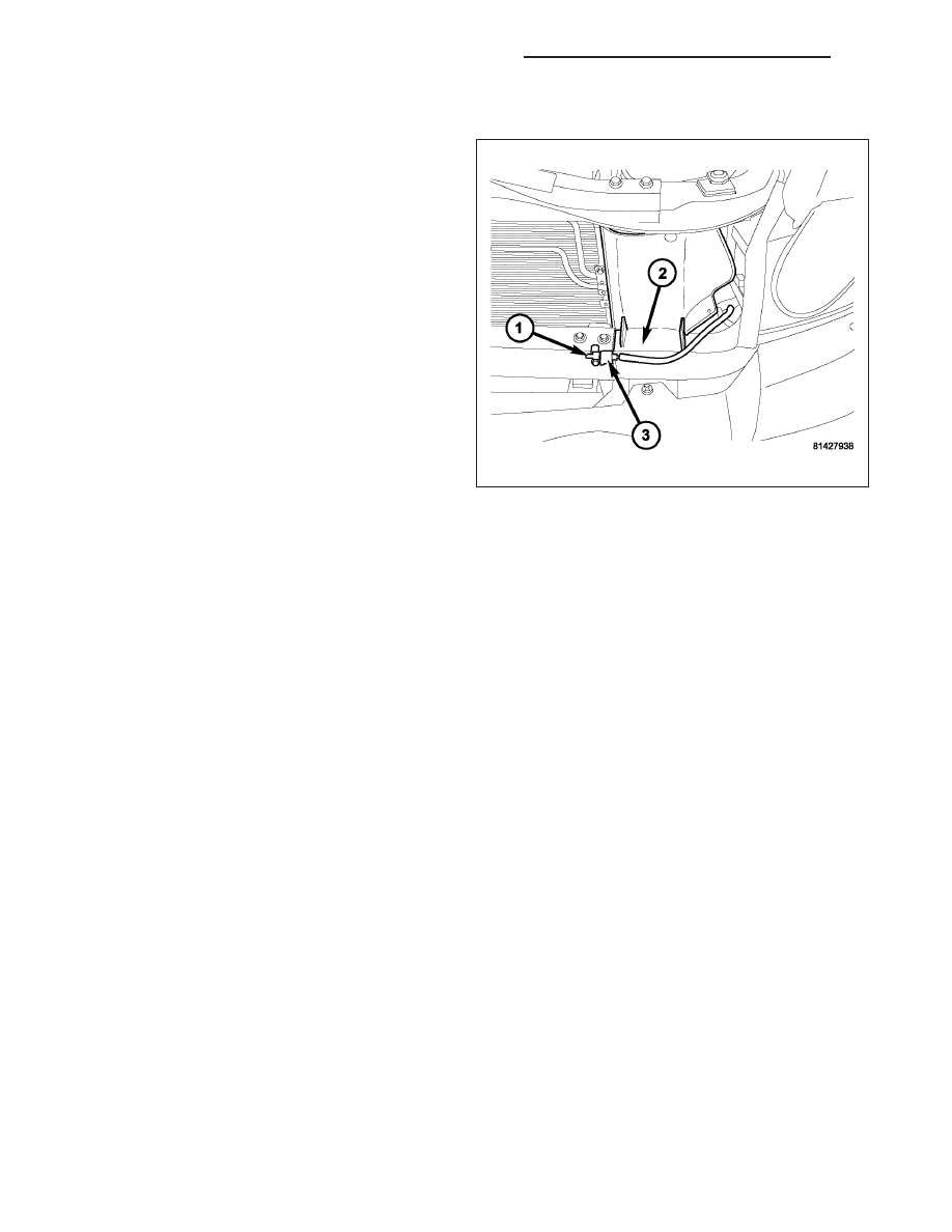
1. Position the ambient temperature sensor (1) onto
the radiator yoke (2).
2. Install the screw that secures the ambient temper-
ature sensor to the radiator yoke. Tighten the
screw to 5.6 N·m (50 in. lbs.).
3. Connect the wire harness connector (3) to the
ambient temperature sensor (1).
4. Reconnect the battery negative cable.
8M - 30
OVERHEAD CONSOLE - SERVICE INFORMATION
ND
POWER SYSTEMS
TABLE OF CONTENTS
page
page
POWER LOCKS - ELECTRICAL DIAGNOSTICS
TABLE OF CONTENTS
page
page
POWER LOCKS - ELECTRICAL DIAGNOSTICS
BODY VERIFICATION TEST – VER 1
*DRIVER DOOR LOCK/UNLOCK SWITCH
INPUT CIRCUIT LOW . . . . . . . . . . . . . . . . . . . 3
*DRIVER DOOR LOCK/UNLOCK SWITCH
INPUT STUCK LOCK . . . . . . . . . . . . . . . . . . . . 6
*DRIVER DOOR LOCK/UNLOCK SWITCH
INPUT STUCK UNLOCK . . . . . . . . . . . . . . . . . 9
INOPERATIVE . . . . . . . . . . . . . . . . . . . . . . . . 12
SWITCH INPUT CIRCUIT LOW . . . . . . . . . . . 16
SWITCH INPUT STUCK LOCK . . . . . . . . . . . . 19
SWITCH INPUT STUCK LOCK . . . . . . . . . . . . 22
INOPERATIVE . . . . . . . . . . . . . . . . . . . . . . . . 25
SHORTED TO GROUND . . . . . . . . . . . . . . . . 29
*ALL DOOR UNLOCK OUTPUT CIRCUIT
SHORTED TO GROUND . . . . . . . . . . . . . . . . 34
*DRIVER DOOR UNLOCK OUTPUT CIRCUIT
SHORTED TO GROUND . . . . . . . . . . . . . . . . 38
*LEFT FRONT LOCKS ONLY – ALL OTHERS
INOPERATIVE . . . . . . . . . . . . . . . . . . . . . . . . 47
UNLOCK – QUAD CAB . . . . . . . . . . . . . . . . . 50
*RIGHT DOORS UNLOCK ONLY – QUAD
CAB . . . . . . . . . . . . . . . . . . . . . . . . . . . . . . . . 53
*RIGHT DOORS LOCK ONLY – QUAD CAB
POWER LOCKS - ELECTRICAL DIAGNOSTICS
DIAGNOSIS AND TESTING
ND
POWER SYSTEMS
8N - 1
BODY VERIFICATION TEST – VER 1
Diagnostic Test
1.
Perform Body Verification Test
Disconnect all jumper wires and reconnect all previously disconnected components and connectors.
Ensure that all accessories are turned off.
Ensure that the battery is fully charged.
Turn the ignition on.
With the scan tool, record and erase DTCs from all modules.
If an electronic control module was replaced, select the applicable module from the scan tool menu and press “Misc.
Functions”. If the module has programable features, program as necessary.
If repairs were made to any of the HVAC door actuator circuits, with the scan tool in HVAC, select System Tests and
then select Actuator DTC Detection. The test must pass before proceeding to the next step.
If repairs were made to any of the HVAC doors, linkage, door actuators, or door actuator circuits, with the scan tool
in HVAC, select System Tests and then select Actuator Calibration Test. The test must pass before proceeding to
the next step.
Turn the ignition off, wait 10 seconds, and then turn the ignition on.
Operate all functions of the system that caused the original concern.
With the scan tool, select ECU View.
Check for DTCs in the modules.
Are DTCs present in any of the modules or is the original condition still present?
Yes
>> The repair is not complete. Refer to the related category for the DTC or symptom that is still present.
No
>> The repair is complete.
8N - 2
POWER LOCKS - ELECTRICAL DIAGNOSTICS
ND
*DRIVER DOOR LOCK/UNLOCK SWITCH INPUT CIRCUIT LOW
ND
POWER LOCKS - ELECTRICAL DIAGNOSTICS
8N - 3
Нет комментариевНе стесняйтесь поделиться с нами вашим ценным мнением.
Текст