Chrysler Le Baron, Dodge Dynasty, Plymouth Acclaim. Manual — part 272
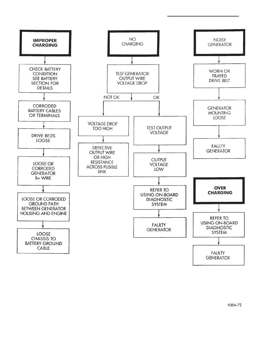
Fig. 1 Charging Diagnostics
8A - 20
BATTERY/STARTING/CHARGING SYSTEMS DIAGNOSTICS
Ä

(5) Connect an engine tachometer and connect bat-
tery negative cable.
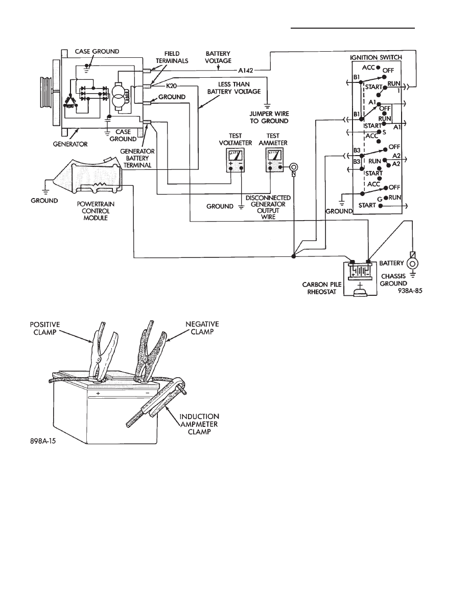
(6) Connect a volt/amp tester equipped with a vari-
able carbon pile rheostat between battery terminals
(Fig. 6). Be sure carbon pile is in OFF position before
connecting leads.
(7) Remove fresh air hose between Powertrain
Control Module computer and air cleaner if neces-
sary.
(8) Full field the generator. Connect a jumper wire
between a good ground and K20 circuit terminal at
the back of the generator (Figs. 2 and 5).
CAUTION: Do not connect the A142 circuit terminal
(Fig. 2) to ground. Fusible link will burn.
TEST
(1) Start the engine. Immediately after starting,
reduce engine speed to idle.
Fig. 2 Generator Wiring Connections
Fig. 3 Generator Output Wire Resistance Test
Fig. 4 Volt/Amp Tester Connections
Ä
BATTERY/STARTING/CHARGING SYSTEMS DIAGNOSTICS
8A - 21
(2) Adjust the carbon pile and engine speed in
steps until an engine speed of 1250 rpm, and a volt-
meter reading of 15 volts is obtained.
CAUTION: Do not allow the battery voltage to ex-
ceed 16 volts.
(3) The generator amperage must meet the output
requirements for the particular generator being
tested. Refer to Generator Specifications for genera-
tor identification and amperage outputs.
RESULTS
(1) If amperage reading is less than specified, and
generator output wire resistance is not found exces-
sive from the previous tests, generator should be re-
placed. Refer to Group 8B, Battery/Starter/Generator
Service, Generator Replacement. These generators
are not intended to be disassembled for service. It
must be replaced as an assembly.
(2) After current output test is completed, reduce
engine speed, turn off carbon pile, and turn off igni-
tion switch.
(3) Disconnect battery negative cable.
(4) Remove test ammeter, voltmeter, tachometer
and carbon pile.
(5) Remove jumper wire between K20 circuit ter-
minal and ground.
(6) Connect output wire to B+ terminal.
(7) Connect negative battery cable.
(8) Connect fresh air hose between powertrain con-
trol module and air cleaner if removed.
Fig. 5 Generator Current Output Test
Fig. 6 Volt/Amp Tester Connections
8A - 22
BATTERY/STARTING/CHARGING SYSTEMS DIAGNOSTICS
Ä
FAULT CODES—ON BOARD DIAGNOSTICS
INDEX
page
page
Diagnostic Testing Using Fault Codes
. . . . . . . . . 24
Drb II Diagnostic Tester
. . . . . . . . . . . . . . . . . . . 24
General Description/Information
. . . . . . . . . . . . . . 23
GENERAL DESCRIPTION/INFORMATION
Another way of diagnosing charging system prob-
lems can be accomplished using the On Board Diag-
nostic System Fault Codes.
A Fault Code shows a potential problem in a mon-
itored circuit,
or a condition caused by a faulty component. A
Fault Code can be retrieved by turning the ignition
switch ON-OFF-ON-OFF-ON without starting the
engine, and counting the number of flashes of the
Malfunction Indicator (CHECK ENGINE) Lamp in
the instrument cluster.
EXAMPLES:
• If the Malfunction Indicator (Check Engine) Lamp
flashes four times, pauses, and flashes one more
time, a Code 41 is shown. The first set of four flashes
indicates number four. The second set of one flash in-
dicates one.
• If the Malfunction Indicator (Check Engine) Lamp
flashes four times, pauses, and flashes six more
times, a Code 46 is shown. The first set of four
flashes indicates number four. The second set of six
flashes indicates six.
• If the Malfunction Indication (Check Engine)
Lamp flashes four times, pauses, and flashes seven
more times, a Code 47 is shown. The first set of four
flashes indicates number four. The second set of
seven flashes indicates seven.
POWERTRAIN CONTROL MODULE
The Powertrain Control Module is equipped with
On Board Diagnostic features and monitors all en-
gine control circuits during a run/drive period. If a
circuit or system does not perform properly, the pow-
ertrain control module will file in memory a preset
Fault Code. This can be used to help in diagnosing a
problem. After 50 to 100 ignition switch ON/RUN cy-
cles, the memory will be erased if the fault does not
reoccur.
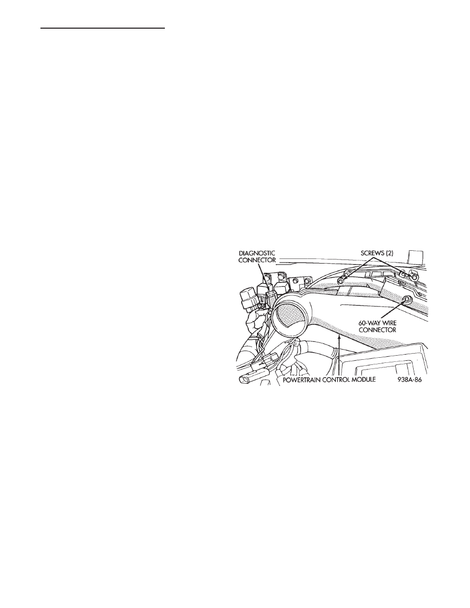
The Powertrain Control Module is located in the
engine compartment outboard of the battery (Fig. 7).
Refer to Fig. 8 Generator Fault Codes Chart for re-
lationships of generator/charging system Fault Code
numbers.
Fig. 7 Powertrain Control Module
Ä
BATTERY/STARTING/CHARGING SYSTEMS DIAGNOSTICS
8A - 23
Нет комментариевНе стесняйтесь поделиться с нами вашим ценным мнением.
Текст