Chrysler Le Baron, Dodge Dynasty, Plymouth Acclaim. Manual — part 209
During the cold start warm-up period and the hot
start time delay, the PCM does not energize the so-
lenoid. When de-energized, no vapors are purged.
The PCM de-energizes the solenoid during open loop
operation.
The engine enters closed loop operation after it
reaches a specified temperature and the time delay
ends. During closed loop operation, the PCM ener-
gizes and de-energizes the solenoid approximately 5
to 10 times per second, depending upon operating
conditions. The PCM varies the vapor flow rate by
changing solenoid pulse width. Pulse width is the
amount of time the solenoid energizes. The PCM ad-
justs solenoid pulse width based on engine air flow.
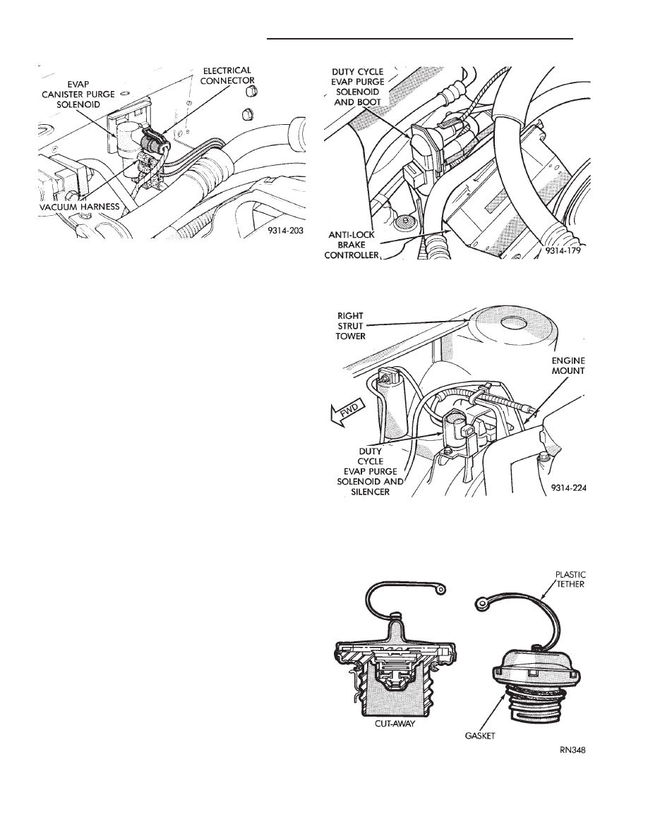
A rubber boot covers the duty cycle EVAP purge
solenoid. On 2.5L MPI flexible fuel AA-body vehicles,
the solenoid and bracket attach to the EVAP canister
mounting studs (Fig. 7). On vehicles with 3.0L en-
gines, the solenoid attaches to a bracket mounted to
the right engine mount (Fig. 8). The top of the sole-
noid has the word TOP on it. The solenoid will not
operate unless it is installed correctly.
PRESSURE-VACUUM FILLER CAP
CAUTION: Remove the fuel filler cap to relieve fuel
tank pressure. Remove the cap before disconnect-
ing fuel system components or servicing the fuel
tank.
A pressure-vacuum relief cap seals the fuel tank
(Fig. 9). Tightening the cap on the fuel filler tube
forms a seal between them. The relief valves in the
cap are a safety feature. They prevent possible exces-
sive pressure or vacuum in the tank. Excessive fuel
tank pressure could be caused by a malfunction in
the system or damage to the vent lines.
The seal between the cap and filler tube breaks
when the cap is removed. Removing the cap breaks
the seal and relieves fuel tank pressure.
If the filler cap needs replacement, only use a sim-
ilar unit.
Fig. 6 Canister Purge Solenoid—Except 3.0L and
2.5L MPI
Fig. 7 Duty Cycle EVAP Purge Solenoid—2.5L MPI
Flexible Fuel AA-Body
Fig. 8 Duty Cycle EVAP Purge Solenoid—3.0L
Engine
Fig. 9 Pressure Vacuum Filler Cap
25 - 14
EMISSION CONTROL SYSTEMS
Ä

POSITIVE CRANKCASE VENTILATION (PCV)
SYSTEMS
Intake manifold vacuum removes crankcase vapors
and piston blow-by from the engine. The emissions pass
through the PCV valve into the intake manifold where
they become part of the calibrated air-fuel mixture.
They are burned and expelled with the exhaust gases.
The air cleaner supplies make up air when the engine
does not have enough vapor or blow-by gases. In this
system, fresh air does not enter the crankcase (Figs. 10,
11, 12, 13, 14, 15, and 16).
PCV VALVE TEST
WARNING:
APPLY
PARKING
BRAKE
AND/OR
BLOCK WHEELS BEFORE PERFORMING ANY TEST
OR ADJUSTMENT WITH THE ENGINE OPERATING.
With the engine idling, remove the PCV valve
from its attaching point. If the valve is operating
properly, a hissing noise will be heard and a strong
vacuum felt when placing a finger over the valve in-
let (Fig. 17). With the engine off, the shake the
valve. The valve should rattle when shaken. Replace
the valve if it does not operate properly. Do not at-
tempt to clean the PCV valve.
Fig. 10 PCV Valve—2.5L TBI Engine
Fig. 11 PCV System—2.5L MPI (Flexible Fuel)
Fig. 12 PCV System—Turbo III Engine
Fig. 13 PCV System—3.0L Engine
Ä
EMISSION CONTROL SYSTEMS
25 - 15
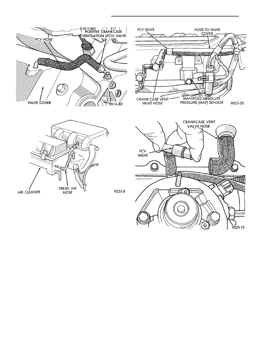
CRANKCASE VENT FILTER
All engines have a crankcase vent filter. The filter
cleans outside air before it enters the PCV system.
On 2.5L engines, the filter mounts to the upper shell
assembly of the air cleaner. On 2.5L MPI (Flexible
Fuel AA-body) and Turbo III engines, the filter at-
taches to the inside of the filter element box, next to
the filter element. On 3.0L engines, it attaches to the
inside of the filter element box under the filter ele-
ment. On the 3.3L engines, the filter mounts to the
bottom of the filter element box. Refer to Group 0 for
mileage intervals and service procedures.
Fig. 14 PCV Valve—3.0L Engine
Fig. 15 PCV System Fresh Air Hose—3.0L Engine
Fig. 16 PCV System—3.3L/3.8L Engines
Fig. 17 Typical PCV Test
25 - 16
EMISSION CONTROL SYSTEMS
Ä
EXHAUST EMISSION CONTROLS
INDEX
page
page
Air Aspiration System
. . . . . . . . . . . . . . . . . . . . . 24
EGR Gas Flow Test
. . . . . . . . . . . . . . . . . . . . . . 21
EGR System On-Board Diagnostics
. . . . . . . . . . . 21
EGR Tube Service—2.2L and 2.5L TBI Engines
. 22
EGR Tube Service—3.0L Engines
. . . . . . . . . . . . 22
EGR Tube Service—3.3L and 3.8L Engines
. . . . 22
EGR Valve Service—2.2L and 2.5L TBI Engines
. 22
EGR Valve Service—3.0L Engines
. . . . . . . . . . . 22
EGR Valve Service—3.3L and 3.8L Engines
. . . . 22
Exhaust Gas Recirculation (EGR) System
. . . . . . 20
Exhaust Gas Recirculation (EGR) System Test
. . 21
Heated Inlet Air System
. . . . . . . . . . . . . . . . . . . 17
Heated Oxygen Sensor (O
2
Sensor)
. . . . . . . . . . 18
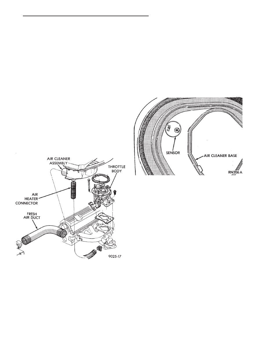
HEATED INLET AIR SYSTEM
2.5L MPI (Flexible Fuel AA-body), Turbo III, 3.0L,
3.3L and 3.8L engines do not use a heated inlet air
system.
2.2L and 2.5L TBI air cleaners have a heated air
assembly (Fig. 1). When ambient temperatures are
low, the assembly warms the air before it enters the
throttle body. The heated air assembly reduces hy-
drocarbon emissions, improves engine warm-up char-
acteristics and minimizes icing.
The heated air assembly contains a vacuum oper-
ated blend door. The blend door opens to either
heated air from a stove on the exhaust manifold or
ambient air (outside air). A vacuum diaphragm oper-
ates the door. A spring opposes the vacuum dia-
phragm. A temperature sensor controls the vacuum
diaphragm (Fig. 2). Adjustment of inlet air tempera-
ture occurs only at road load throttle positions or
when the intake manifold vacuum exceeds the vac-
uum diaphragm spring rate.
Air flows through the outside air inlet when ambi-
ent air temperature is 8°C (15°F) or more above the
air temperature sensor control temperature.
When ambient air temperature falls below the con-
trol temperature, air flows through both the ambient
and heated circuits. This occurs after the engine has
been started and the exhaust manifold starts to give
off heat. Colder ambient air cause greater air flow
through the heat stove on the exhaust manifold.
Warmer ambient air results in greater ambient air
flow through the air cleaner snorkel.
HEATED INLET AIR SYSTEM SERVICE
Heated air inlet system malfunctions may affect
driveability and vehicle exhaust emissions.
Use the following procedure to determine if the
system functions properly.
(1) Inspect the condition of the heat stove to air
cleaner flexible connector and all vacuum hoses. In-
spect them for proper attachment. Replace as neces-
sary.
(2) With a cold engine and ambient temperature
less than 46°C (115°F.), the heat control door (valve
plate) should be in the up (heat on position).
(3) With the engine warmed up and running,
check the temperature of the air entering the snorkel
or passing the sensor. When the temperature of the
Fig. 1 Heated Air Inlet System
Fig. 2 Heated Air Temperature Sensor
Ä
EMISSION CONTROL SYSTEMS
25 - 17
Нет комментариевНе стесняйтесь поделиться с нами вашим ценным мнением.
Текст