Chrysler Le Baron, Dodge Dynasty, Plymouth Acclaim. Manual — part 128
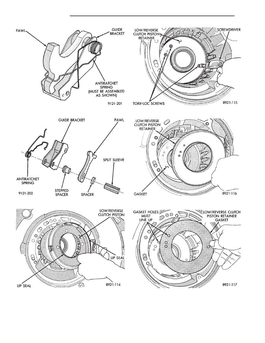
Fig. 76 Guide Bracket Assembled
Fig. 77 Guide Bracket Disassembled
Fig. 78 Low/Reverse Clutch Piston
Fig. 79 Piston Retainer Attaching Screws
Fig. 80 Piston Retainer
Fig. 81 Piston Retainer Gasket
21 - 118
TRANSAXLE
Ä
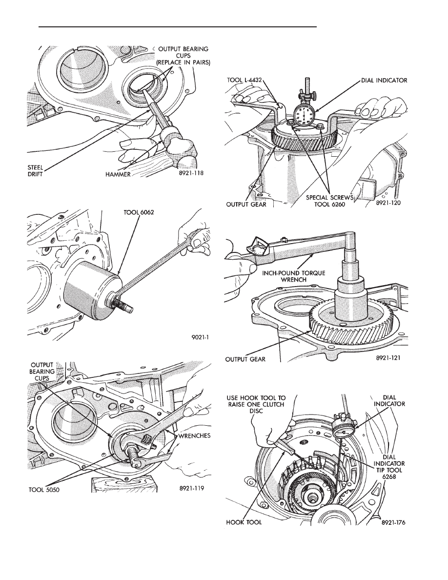
CAUTION: Drift bearing cup all the way around.
To assemble, reverse the above procedure. Be sure
to check both grounded clutch clearances. Before in-
stalling the input clutches retainer, follow the instruc-
tions in Determining No. 4 Thrust Plate Thick-
ness.
Fig. 82 Remove Output Bearing Inner Cup
Fig. 83 Remove Output Bearing Outer Cup
Fig. 84 Install Both Output Bearing Cups
Fig. 85 Checking Output Gear Bearings End Play
Fig. 86 Checking Output Gear Bearings Turning
Torque
Fig. 87 Check Low/Reverse Clutch Clearance
Ä
TRANSAXLE
21 - 119
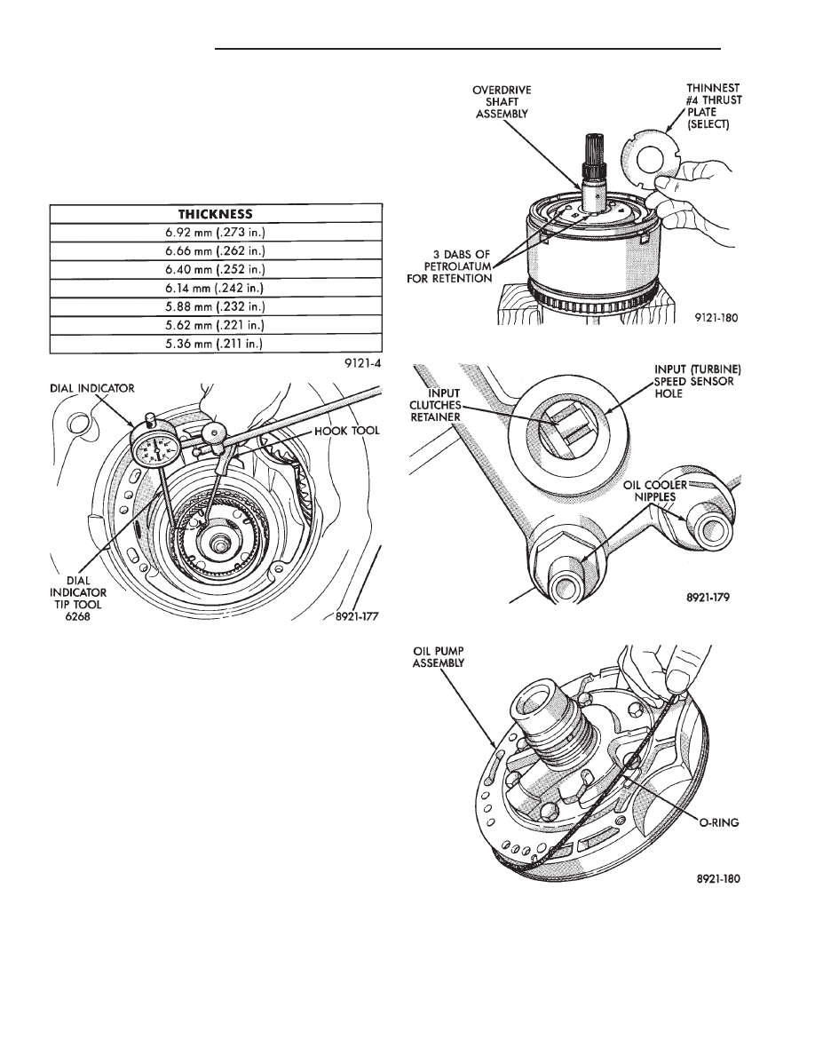
Press down clutch pack with finger and zero dial
indicator. Low/Reverse clutch pack clearance is
1.04 to 1.65mm (.042 to .065 inch).
Select the proper low/reverse reaction plate to
achieve specifications:
Press down clutch pack with finger and zero dial
indicator. The 2/4 clutch pack clearance is 0.76 to
2.64mm (.030 to .104 inch). If not within specifica-
tions, the clutch is not assembled properly. There is
no adjustment for the 2/4 clutch clearance.
DETERMINING NO. 4 THRUST PLATE
THICKNESS—INPUT SHAFT END PLAY
To determine the proper thickness of the No. 4 thrust
plate, select the thinnest No. 4 thrust plate. Using
petrolatum (Fig. 87) to hold thrust plate in position,
install input clutches assembly. Be sure the input
clutches assembly is completely seated (Fig. 88).
CAUTION: If view through input speed sensor hole is
not as shown above, the input clutches assembly is
not seated properly.
By removing the oil pump O-ring, you will be able to
install and remove the oil pump and gasket very easily
to select the proper No. 4 thrust plate.
CAUTION: Be sure to reinstall O-ring on oil pump
after selecting the proper No. 4 thrust plate.
Input shaft end play must be .005 to .025 inch.
LOW/REVERSE REACTION PLATE CHART
Fig. 88 Check 2/4 Clutch Clearance
Fig. 89 Select Thinnest No. 4 Thrust Plate
Fig. 90 View Through Input Speed Sensor Hole
Fig. 91 Remove Oil Pump O-Ring
21 - 120
TRANSAXLE
Ä
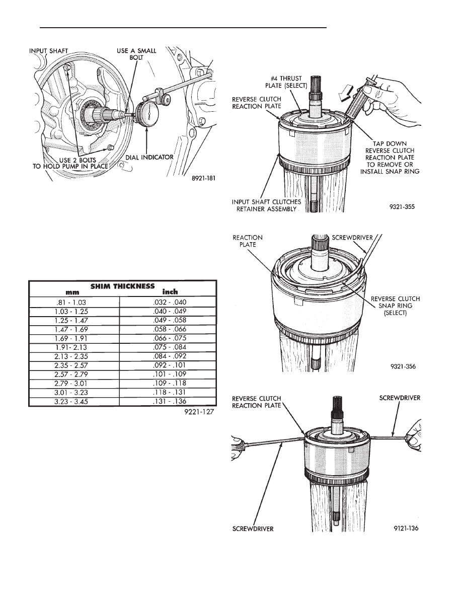
For example, if end play reading is .055 inch, select
No. 4 Thrust Plate which is .071 to .074 thick. This
should provide an input shaft end play reading of
.020 inch which is within specifications.
See chart below to select the proper No. 4 thrust
plate.
INPUT CLUTCHES-RECONDITION
DISASSEMBLY
Fig. 92 Measure Input Shaft End Play
NO. 4 THRUST PLATE CHART
Fig. 1 Tapping Reaction Plate
Fig. 2 Reverse Clutch Snap Ring
Fig. 3 Pry Reverse Clutch Reaction Plate
Ä
TRANSAXLE
21 - 121
Нет комментариевНе стесняйтесь поделиться с нами вашим ценным мнением.
Текст