Chrysler Le Baron, Dodge Dynasty, Plymouth Acclaim. Manual — part 236

card the old retainer clip, a new clip must be
used when hydraulic assembly is reinstalled
(Fig. 8).
(10) Remove the 4 hydraulic assembly to dash
panel mounting nuts from the hydraulic assembly
mounting studs, located under instrument panel (Fig.
8).
(11) Remove hydraulic assembly from vehicle.
INSTALL
(1) Position the hydraulic assembly into its mount-
ing holes on the dash panel of the vehicle.
(2) Install and tighten the 4 hydraulic assembly to
dash panel mounting stud nuts (Fig. 8) to 28 N
Im
(250 in. lbs.) torque.
(3) Using lubriplate or equivalent, coat the bearing
surface of the brake pedal pin.
(4) Connect push rod to pedal pin and install a
NEW retainer clip. HYDRAULIC ASSEMBLY
PUSH ROD MUST BE ASSEMBLED TO BRAKE
PEDAL PIN IN THE POSITION AS SHOWN IN
(FIG. 8).
(5) If proportioning valves were removed from the
hydraulic assembly, install and torque to 40 N
Im (30
ft. lbs.) torque. Then install all 4 brake tubes on the
hydraulic assembly (Fig. 7). Torque the brake tubes
to hydraulic assembly fittings to 16 N
Im (145 in.
lbs.).
(6) Install return hose on steel tube. Tighten the
return hose clamp to 1 N
Im (10 in.lbs.)
Fig. 7 Brake Tube and Hose Routing at Hydraulic
Unit
Fig. 8 Removing or Installing Hydraulic Assembly
5 - 98
ANTI-LOCK 10 BRAKE SYSTEM
Ä
(7) Install high pressure hose to hydraulic assem-
bly (Fig. 7). Tighten the hose, to hydraulic assembly
fitting to 16 N
Im (145 in. lbs)
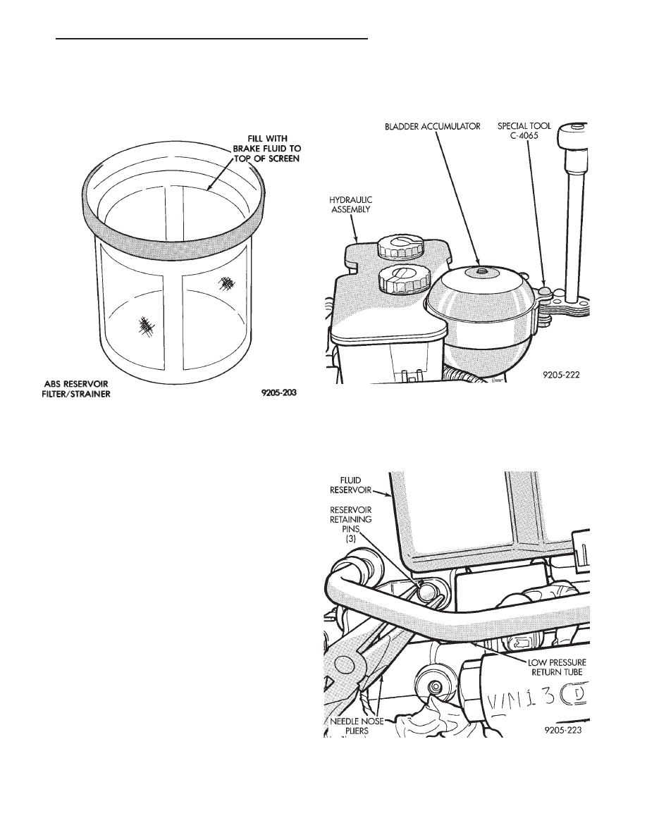
(8) Fill hydraulic assembly brake fluid reservoir to
top of screen on the reservoir filter/strainer Fig. 9.
(9) Connect all electrical connectors to the hydrau-
lic assembly.
(10) Bleed the entire brake system, see Bleeding
Brake System in this section of the Service Manual.
(11) Replace all fresh air intake ducts, air cleaner
and washer bottle.
(12) Check that the brake fluid in the hydraulic
assembly is at the correct level before moving vehicle
(Fig. 9). (See Checking Brake Fluid Level in this sec-
tion of the service manual).
BRAKE FLUID RESERVOIR
REMOVE
(1) Fully de-pressurize the hydraulic accumulator
by pumping brake pedal a minimum of 40 times. Use
procedure described in De-Pressurizing Hydraulic Ac-
cumulator listed earlier in this section.
WARNING: FAILURE TO DE-PRESSURIZE HYDRAU-
LIC ACCUMULATOR, BEFORE PERFORMING THIS
OPERATION, MAY RESULT IN PERSONAL INJURY
AND/OR DAMAGE TO PAINTED SURFACES.
(2) Remove as much brake fluid as possible from
the fluid reservoir, using a syringe or equivalent
method.
(3) Using Oil Filter Band Wrench, Special Tool
C-4065 or equivalent loosen bladder accumulator.
Then remove the bladder accumulator and brake
fluid spray shield from the hydraulic assembly (Fig.
10). Remove high pressure banjo fitting from hydrau-
lic assembly.
(4) Using needle nose pliers, remove the three
fluid reservoir retaining pins from the hydraulic as-
sembly (Fig. 11). Compress the barb on the opposite
side of retaining pin to prevent pin from breaking.
(5) Remove reservoir from hydraulic assembly by
CAREFULLY prying between reservoir and hydrau-
Fig. 9 ABS Fill Level On Filter/Strainer
Fig. 10 Removing Bladder Accumulator
Fig. 11 Remove Reservoir Retaining Pins
Ä
ANTI-LOCK 10 BRAKE SYSTEM
5 - 99
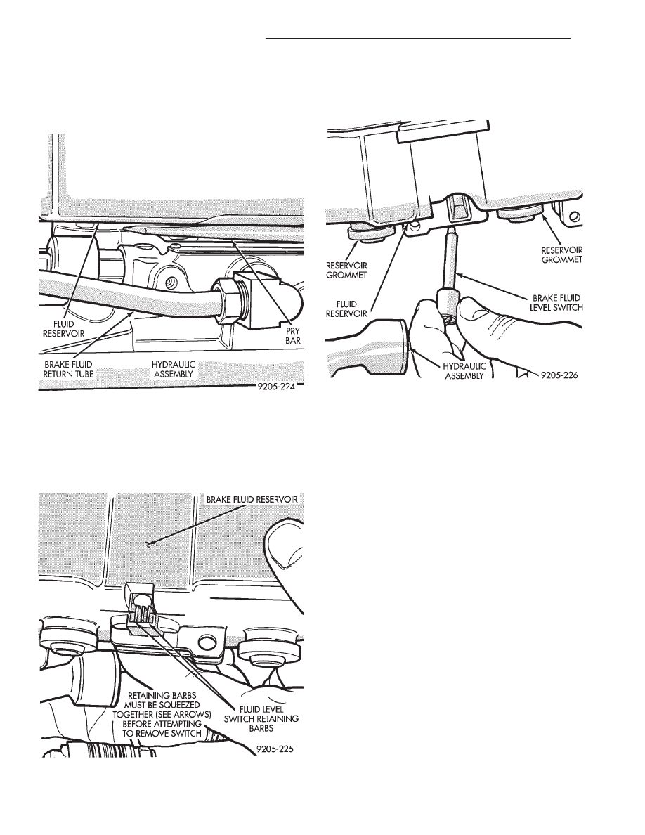
lic assembly with a blunt prying tool (Fig. 12). Use a
rocking motion to help disengage reservoir from
grommets while prying. BE EXTREMELY CARE-
FUL TO AVOID DAMAGING OR PUNCTURING
RESERVOIR DURING THIS PROCEDURE.
(6) Remove the brake fluid level sensor switch
from the reservoir. Remove switch by compressing
the retaining barbs (Fig. 13) on the end of the switch
and then slide switch out of the brake fluid reservoir
(Fig. 14)
(7) Using fingers, remove the 3 reservoir grommets
(Fig. 14) from the hydraulic assembly or reservoir, and
discard. Grommets must not to be reused when
reservoir is installed on hydraulic assembly.
INSTALL
(1) Thoroughly lubricate the new reservoir grom-
mets with clean brake fluid and install on reservoir
outlet ports (Fig. 14). The new reservoir grommets
supplied with reservoir, must ALWAYS be used.
(2) Install brake fluid level switch into brake fluid
reservoir (FIG. 14).
(3) Press reservoir into hydraulic assembly BY
HAND, using a rocking motion to help seat reservoir
into hydraulic assembly. Be sure that grommets are
fully seated in the hydraulic assembly. DO NOT AT-
TEMPT TO POUND RESERVOIR INTO HY-
DRAULIC ASSEMBLY, USING A HAMMER.
(4) Using needle nose pliers, install the 3 brake fluid
reservoir to hydraulic assembly retaining pins (Fig.
11). Make sure that pins are fully installed with barbs
extending past reservoir on opposite side.
(5) Reinstall the high pressure hose, banjo fitting
onto the hydraulic assembly and torque the fitting to
13 N
Im (10.0 ft.lbs).
(6) Install the brake fluid spray shield and bladder
accumulator onto the hydraulic assembly. Install the
bladder accumulator by hand to be sure it does not bet
cross threaded. Be sure that the O-Ring on the
bladder accumulator is fully seated into the hy-
draulic assembly.
(7) Using Oil Filter Band Wrench, Special Tool C-
4065 or equivalent, (Fig. 10) torque the bladder accu-
mulator to 48 N
Im (35 ft. lbs.)
Fig. 12 Remove Reservoir From Hydraulic Assembly
Fig. 13 Fluid Switch Retaining Barbs
Fig. 14 Remove Brake Fluid Level Switch
5 - 100
ANTI-LOCK 10 BRAKE SYSTEM
Ä

(8) Fill the hydraulic assembly reservoir to the top
of the screen on the filter/strainer (Fig. 15). Using
fresh clean brake fluid such as Mopar
t or equivalent,
conforming to DOT 3 requirements.
PUMP SUPPLY FILTER
REMOVE
(1) Fully de-pressurize the hydraulic accumulator
by pumping brake pedal a minimum of 40 times. Use
procedure described in De-Pressurizing Hydraulic Ac-
cumulator listed earlier in this section.
WARNING: FAILURE TO DE-PRESSURIZE HYDRAU-
LIC ACCUMULATOR, BEFORE PERFORMING THIS
OPERATION, MAY RESULT IN PERSONAL INJURY
AND/OR DAMAGE TO PAINTED SURFACES.
(2) Remove and then reinstall one filler cap from
brake fluid reservoir on hydraulic assembly.
(3) Remove brake fluid supply hose from hydraulic
assembly master cylinder at the pump supply filter
(Fig. 16). After hose is removed from pump supply
filter, plug end of hose to stop brake fluid from drain-
ing out of fluid reservoir.
(4) Remove brake fluid supply hose (Fig. 16), from
pump supply filter going to the pump motor assem-
bly.
(5) Remove pump supply filter (Fig. 16) from at-
taching bracket on front of hydraulic assembly.
INSTALL
(1) Attach pump supply filter to attaching bracket
on front of hydraulic assembly (Fig. 16).
(2) Install replacement hose clamp, on brake fluid
supply hose to pump motor assembly.
(3) Install the brake fluid supply hose to pump mo-
tor assembly, onto the nipple of the pump supply fil-
ter. Position hose clamp on brake fluid supply hose
so that it is past upset bead on nipple, then torque
hose clamp to 1.5 N
Im (13.5 in. lbs.).
(4) Remove plug from brake fluid supply hose com-
ing from hydraulic assembly. Install the brake fluid
supply hose from hydraulic assembly, onto the nipple
of the pump supply filter. Position hose clamp on
brake fluid supply hose so that it is past upset bead
on nipple, then torque hose clamp to 1.5 N
Im (13.5
in. lbs.).
(5) Turn ignition switch to the run position to en-
ergize the pump/motor assembly and pressurize hy-
draulic system. Check for leakage at the hydraulic
assembly to hydraulic bladder accumulator fitting.
(6) Again de-pressurize accumulator by pumping
brake pedal a minimum of 40 times as described. Use
procedure in De-Pressurizing Hydraulic Accumulator
in this section of the manual.
(7) Then check the brake fluid level in the hydrau-
lic assembly reservoir. If brake fluid level is low, fill
reservoir to proper level (Fig. 15) with Mopar
t brake
fluid or equivalent conforming to DOT 3 require-
ments.
HYDRAULIC BLADDER ACCUMULATOR
REMOVE
(1) Fully de-pressurize the hydraulic accumulator
by pumping brake pedal a minimum of 40 times. Use
procedure described in De-Pressurizing Hydraulic Ac-
cumulator listed earlier in this section.
Fig. 15 ABS Reservoir Fill Level On Filter/Strainer
Fig. 16 Pump Supply Filter
Ä
ANTI-LOCK 10 BRAKE SYSTEM
5 - 101
Нет комментариевНе стесняйтесь поделиться с нами вашим ценным мнением.
Текст