Chrysler Le Baron, Dodge Dynasty, Plymouth Acclaim. Manual — part 68
(2) Using a lint free towel, wipe clean open power
steering hose ends, power steering pump and steer-
ing gear ports.
(3) Install new O-rings or sealing washers on the
ends of the power steering hoses. Lubricate O-rings
or sealing washers using clean power steering fluid.
(4) Attach power steering hose to proper connec-
tions at power steering pump and steering gear. Cor-
rectly route power steering hoses avoiding tight
bends or kinking of the hose. Install power steering
hose to crossmember routing bracket. Hoses must
remain away from exhaust system, vehicle com-
ponents and unfriendly surfaces causing pos-
sible damage to power steering hoses.
(5) Tighten all fasteners shown for specific applica-
tions in (Fig. 1 to 4) to their correct torques listed
below:
• Pump End Banjo Bolt — 34 NIm (25 ft. lbs.)
• Pump End Tube Nut — 34 NIm (25 ft. lbs.)
• Gear End Tube Nuts (2) — 34 NIm (25 ft. lbs.)
• Crossmember Bracket Bolt — 23 NIm (17 ft. lbs.)
• Pump Bracket Nut — 40 NIm (30 ft. lbs.)
• Gear Bracket Bolt — 68 NIm (50 ft. lbs.)
(6) Install vehicle’s wiring harness connector (if ap-
plicable to vehicle being serviced) onto the power
steering pressure switch (Fig. 1 & 2).
(7) When used, protective sponge sleeves must be
properly positioned on power steering hoses. This is to
prevent hose contact with other components.
(8) After hose is installed, check for leaks. (See
Pump Installation).
POWER STEERING PUMP REMOVAL
WARNING: POWER STEERING OIL, ENGINE COMPO-
NENTS AND
EXHAUST
SYSTEM
MAY BE
EX-
TREMELY HOT IF ENGINE HAS BEEN RUNNING. DO
NOT START ENGINE WITH ANY LOOSE OR DISCON-
NECTED HOSES, OR ALLOW HOSES TO TOUCH HOT
EXHAUST MANIFOLD OR CATALYST.
2.2 & 2.5 LITER
REMOVE
(1) Remove battery cable from (-) negative post on
battery and isolate cable.
(2) Loosen power steering pump adjustment bolt
and rotate power steering pump forward in bracket.
Remove power steering pump drive belt from power
steering pump (Fig. 1). It is not necessary to remove
power steering pump drive belt from engine.
(3) Raise vehicle See Hoisting, Group 0. Remove
hose clamp and low pressure fluid hose from power
steering pump (Fig. 2).
(4) Remove power steering fluid pressure line (Fig.
2) from power steering pump. Drain excess power
steering fluid from line.
(5) Loosen but do not remove nut, holding back of
power steering pump to its mounting bracket (Fig. 3).
Then remove bolt attaching pulley side of power steer-
ing pump to the mounting bracket (Fig. 3).
(6) Lower Vehicle. Then remove bolt, retaining
power steering pump in adjusting slot of power steer-
ing pump mounting bracket (Fig. 3).
(7) Remove power steering pump from top of engine
compartment,
using
the
following
procedure.
Lifting
power
steering
pump
out
of
mounting
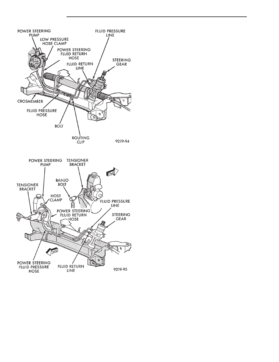
Fig. 5 Power Steering Hose Routing 3.3 & 3.8L
Fig. 6 Power Steering Hose Routing Turbo III
19 - 12
STEERING
Ä
bracket, rotating pump 90° and remove it out be-
tween engine and dash panel.
(8) Transfer required parts from removed power
steering pump, to replacement power steering pump.
INSTALL
(1) Install power steering pump back in vehicle in
the reverse order of removal.
(2) Install power steering pump back on mounting
bracket, being sure stud on back of power steering
pump is in slotted hole in mounting bracket. Install
bolt attaching power steering pump to adjusting slot
in bracket (Fig. 3), but do not tighten nut or bolt.
(3) Raise vehicle See Hoisting, Group 0.
(4) Install bolt attaching pulley side of power
steering pump to power steering pump mounting
bracket (Fig. 3). Do not fully tighten power steer-
ing pump mounting bolts at this time.
(5) Install power steering fluid pressure line into
output fitting on power steering pump (Fig. 2).
Torque power steering pressure line tube nut to 31
N
Im (275 in. lbs.). Before connecting pressure line
to power steering pump inspect O-ring on pres-
sure line for damage and replace if required.
(6) Install power steering fluid, low pressure re-
turn hose on power steering pump low pressure fit-
ting (Fig. 2). Install hose clamp on low pressure
return hose, being sure hose clamp is installed on
hose past upset bead on power steering pump tube.
(7) Lower vehicle.
(8) Install power steering pump drive belt on
power steering pump pulley. Using power steering
pump adjusting bracket (Fig. 1), rotate pump in
bracket to obtain correct belt tension. Tighten bolt at
power steering pump mounting bracket adjusting slot
(Fig. 1) to 54 N
Im (40 ft. lbs.). Torque the power
steering pump to mounting bracket pivot, nut and
bolt (Fig. 1) to 54 N
Im (40 ft. lbs.).
CAUTION: Do not use automatic transmission fluid
in power steering system. Only use Mopar
T
, Power
Steering Fluid, or equivalent.
(9) Fill power steering pump reservoir to correct
fluid level.
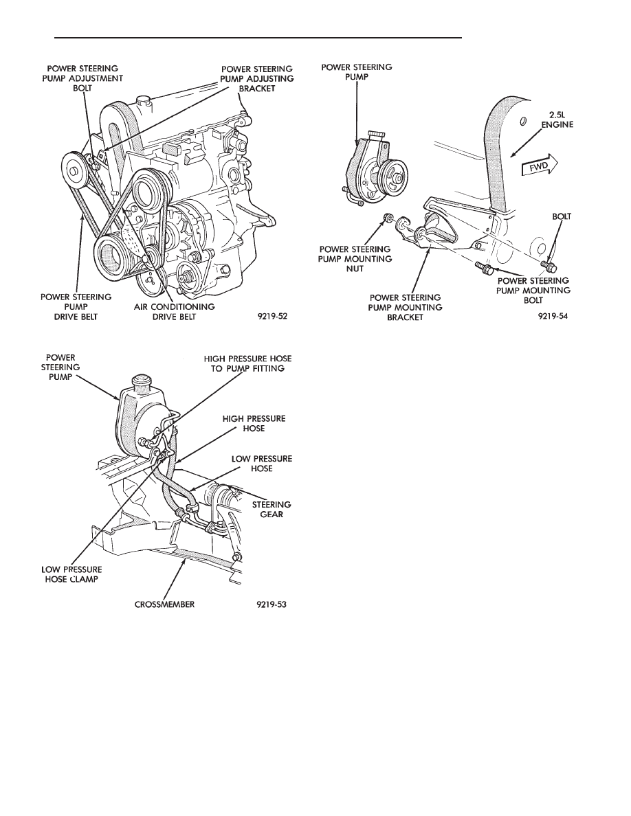
Fig. 1 Power Steering Pump Drive Belt Removal
Fig. 2 Power Steering Fluid Hoses
Fig. 3 Power Steering Pump Remove And Install
Ä
STEERING
19 - 13
(10) Connect negative cable back on negative post
of battery.
(11) Start engine and turn steering wheel several
times from stop to stop to bleed air from fluid in sys-
tem. Stop engine, check fluid level, and inspect sys-
tem for leaks. See Checking Fluid Level.
3.0 LITER
REMOVE
(1) REMOVE THE (-) NEGATIVE BATTERY CA-
BLE FROM THE BATTERY AND ISOLATE CA-
BLE.
(2) Remove the serpentine accessory drive belt
from engine (Fig. 4). See Cooling, Group 7 for de-
tailed removal procedure.
(3) Remove the hose clamp and bolt mounting the
power steering pump filler tube and dipstick assem-
bly (Fig. 5) to power steering pump and generator
bracket. Remove filler tube and dipstick assembly
from power steering pump.
(4) Raise vehicle See Hoisting, Group 0.
(5) Remove the 2 nut, bolt and spring assemblies
attaching the exhaust pipe to exhaust manifold. Re-
move exhaust pipe from exhaust manifold and move
to left side of vehicle. This is required for clear-
ance to remove power steering pump from vehi-
cle.
(6) Remove vehicle’s wiring harness connector (if
applicable to vehicle being serviced) from the power
steering pressure switch (Fig. 6).
(7) Put oil drain pan under vehicle to catch power
steering fluid. Remove hose clamp and low pressure
fluid hose, from power steering gear fluid tube (Fig.
7). Allow excess power steering fluid to drain from
power steering pump and hose.
(8) Loosen the high pressure power steering fluid
line fitting at the power steering pump (Fig. 7). Then
remove high pressure power steering fluid line from
power steering pump.
(9) Remove nut holding the power steering pump
rear support bracket to pump (Fig. 8). Then remove
the 2 bolts (Fig. 7) mounting the power steering
pump support bracket to engine and remove bracket
from vehicle.
(10) Remove the 2 bolts that mount the front of
the power steering pump to the mounting plate (Fig.
9). Access to the mounting bolts is through the holes
in power steering pump pulley using a deep well
socket.
(11) Remove the power steering pump and pulley
assembly from vehicle. Remove pump assembly from
vehicle in area between floor pan and front suspen-
sion crossmember. Pump will fit through area of ex-
haust pipe tunnel in floor pan.
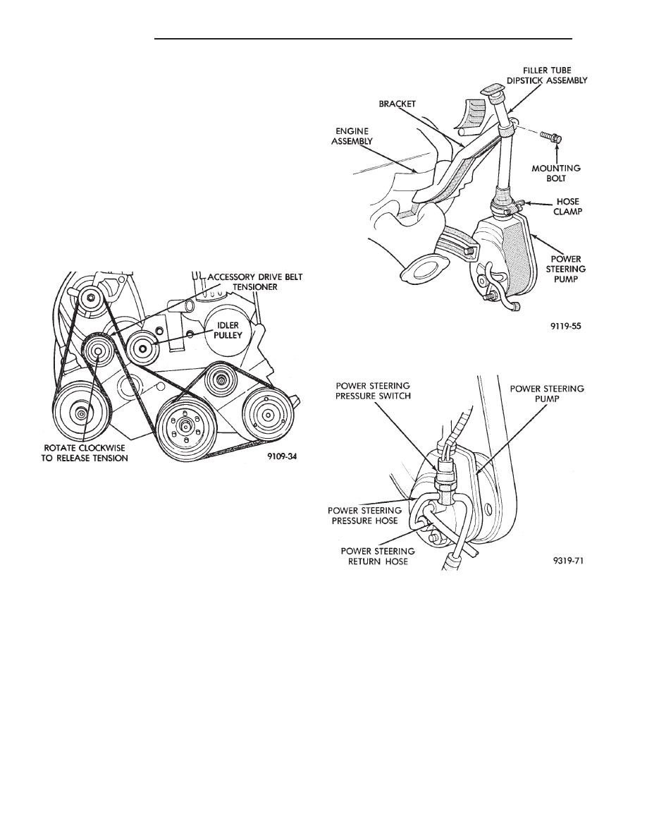
Fig. 4 3.0L Serpentine Drive Belt Routing
Fig. 5 Power Steering Pump Filler Tube/Dipstick
Assembly
Fig. 6 Power Steering Pressure Switch Location
3.0L
19 - 14
STEERING
Ä
(12) Transfer Required parts to the new power
steering pump assembly before installing in vehicle.
INSTALL
(1) Install the power steering pump assembly back
in vehicle in reverse order of removal.
(2) Hold power steering pump against mounting
plate. Align power steering pump mounting holes
with mounting holes in plate and install bolts (Fig.
9). Torque the 2 power steering pump to mounting
plate bolts to 54 N
Im (40 ft. lbs.).
(3) Install the rear power steering pump to engine
block support bracket, onto the stud on back of power
steering pump (Fig. 8). Then install the 2 bolts
mounting the support bracket to the engine block.
Torque the 2 support bracket to engine block mount-
ing bolts to 54 N
Im (40 ft. lbs.).
(4) Install the nut on stud of power steering pump
attaching pump to rear support bracket (Fig. 8).
Torque nut to 54 N
Im (40 ft. lbs.)
(5) Install the high pressure power steering fluid
line on the power steering pump outlet fitting (Fig.
7). Torque the high pressure fluid line to power
steering pump fitting to 31 N
Im (275 in. lbs.).
(6) Install the low pressure power steering fluid
hose onto the power steering gear fluid tube (Fig. 7).
Install hose clamp on hose. Be sure hose clamp is
installed beyond upset bead on tube.
(7) Install the exhaust pipe back on the exhaust
manifold. Install the nut, bolt and spring assemblies
and torque bolts to 28 N
Im (250 in. lbs.).
(8) Install vehicle’s wiring harness connector (if
applicable to vehicle being serviced) onto the power
steering pressure switch (Fig. 6).
(9) Lower vehicle.
(10) Install the power steering pump filler tube
and dip stick assembly on the neck of the power
steering pump (Fig. 5). Install the bolt (Fig. 5) at-
taching the filler tube/dip stick assembly to the gen-
erator bracket, then torque bolt to 11 N
Im (100 in.
lbs.).
(11) Position the hose clamp on the filler tube as-
sembly rubber boot and adequately tighten hose
clamp.
(12) Install the serpentine accessory drive belt on
engine (Fig. 4). See Cooling, Group 7 for detailed in-
stallation procedure.
CAUTION: Do not use automatic transmission fluid
in power steering system. Only use Mopar
T
, Power
Steering Fluid, or equivalent.
(13) Fill power steering pump reservoir to correct
fluid level.
(14) Connect the negative battery cable back on
the negative battery post.
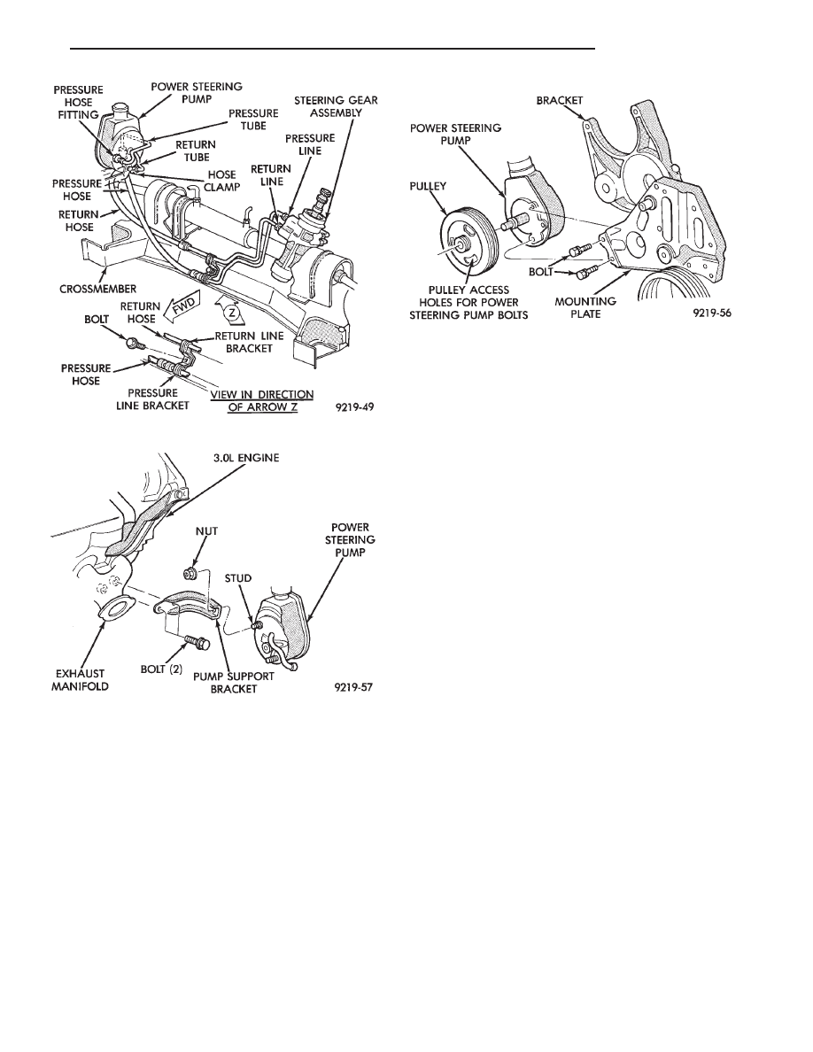
Fig. 7 Power Steering Hose Remove/Replace
Fig. 8 Power Steering Support Bracket
Fig. 9 Power Steering Pump Mounting 3.0L
Ä
STEERING
19 - 15
Нет комментариевНе стесняйтесь поделиться с нами вашим ценным мнением.
Текст