Chrysler Le Baron, Dodge Dynasty, Plymouth Acclaim. Manual — part 25
INSTALLATION
WARNING: FUEL TANKS DESIGNED FOR GASO-
LINE ONLY VEHICLES CANNOT BE USED ON
FLEXIBLE FUEL AA-BODY VEHICLES. WHEN SER-
VICING THE FUEL SYSTEM OF A FLEXIBLE FUEL
VEHICLE, ONLY USE ORIGINAL EQUIPMENT OR
EQUIVALENT REPLACEMENT COMPONENTS.
(1) Position fuel tank on transmission jack. Con-
nect vapor separator/rollover valve hose and position
insulator pad on fuel tank. Position vapor vent so
that it is not pinched between tank and floor pan
during installation.
(2) Raise tank and fuel filler tube carefully into
position. Use a light coating of power steering fluid
to ease fuel filler tube installation. Ensure filler tube
grommet is not damaged. Verify that the tube is in-
stalled correctly.
(3) Tighten fuel tank strap nuts to 23 N
Im (250 in.
lbs.)
torque.
Remove
transmission
jack.
Ensure
straps are not twisted or bent.
(4) Lubricate the metal tubes on the fuel pump
with clean 30 weight engine oil. Install the quick
connect fuel fittings. Refer to Quick Connect Fittings
in the Fuel Delivery section of this Group.
(5) Attach electrical connector to fuel pump mod-
ule and level sensor unit.
(6) Lower the vehicle.
(7) Attach filler tube to filler neck opening in
quarter panel. Tighten quarter panel screws to 2
N
Im (17 in. lbs.) torque.
(8) Fill fuel tank, install filler cap, and connect
battery cable.
CAUTION: When using the ASD Fuel System Test,
the Auto Shutdown (ASD) Relay remains energized
for either 7 minutes, until the test is stopped, or un-
til the ignition switch is turned to the Off position.
(9) Use the DRBII scan tool ASD Fuel System Test
to pressurize the fuel system. Check for leaks.
FUEL PUMP MODULE
Refer to the Fuel Delivery section of this group.
METHANOL CONCENTRATION SENSOR
Refer to the Fuel Delivery section of this group.
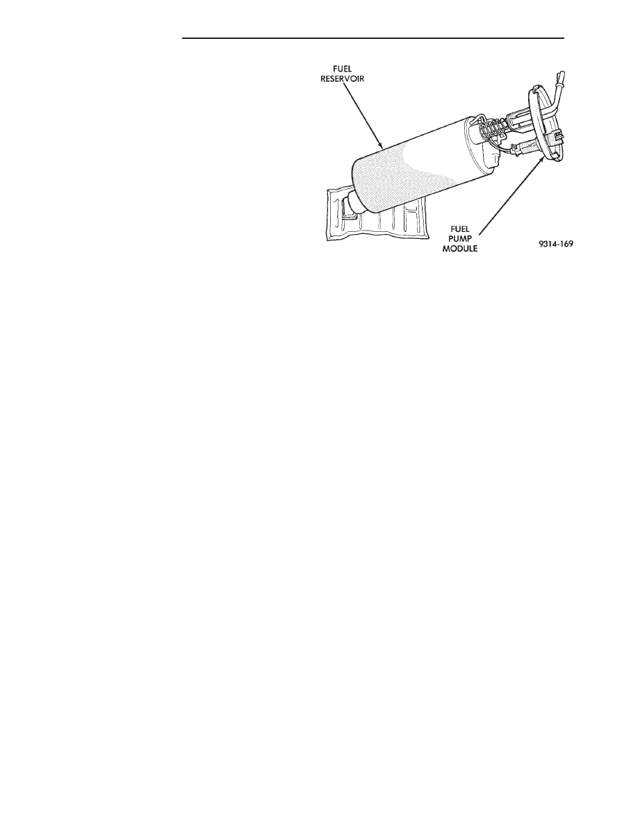
FUEL RESERVOIR
The fuel reservoir is internal to the fuel pump as-
sembly (Fig. 6). The purpose is to provide fuel at the
fuel pump intake during all driving conditions, espe-
cially when low fuel levels are present.
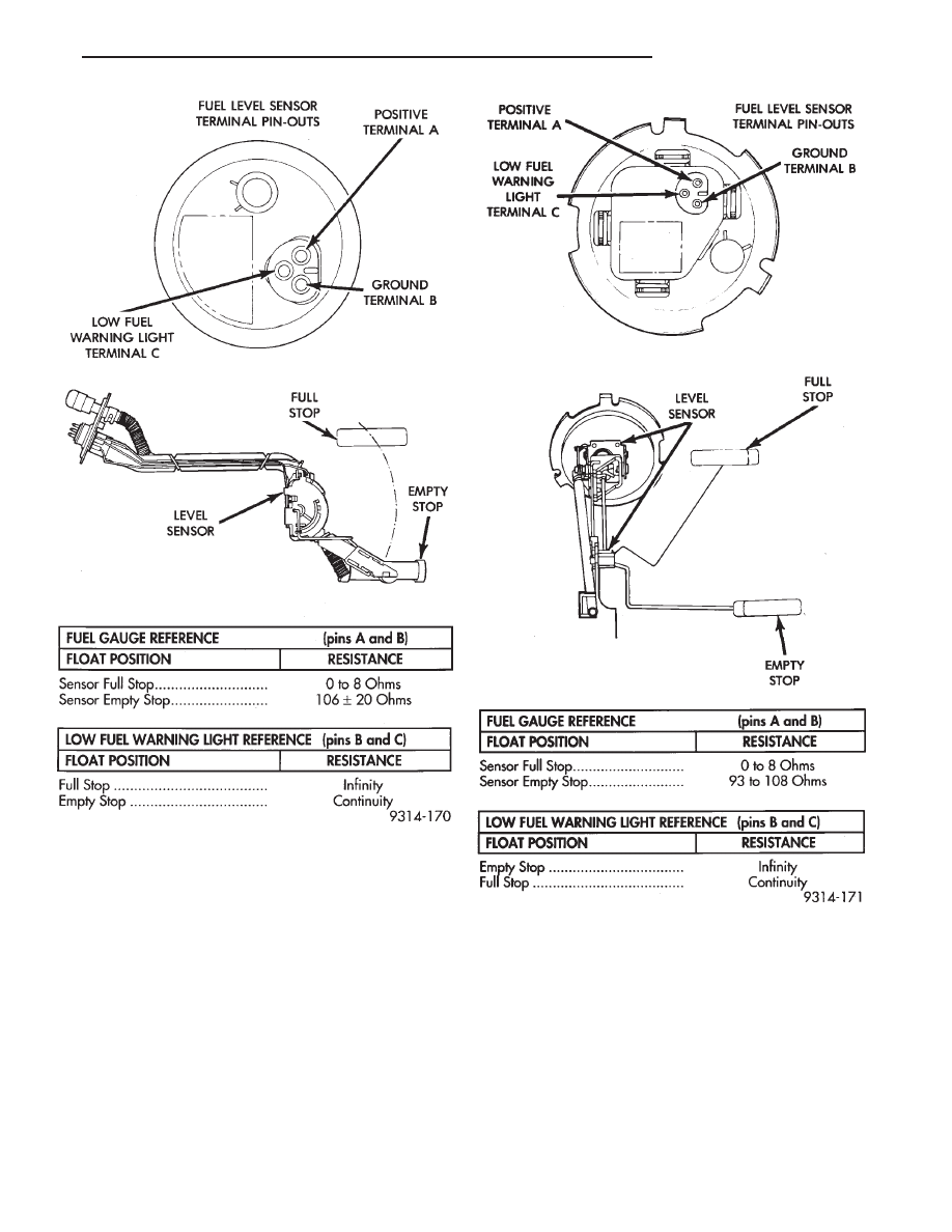
FUEL TANK LEVEL SENSOR
DIAGNOSIS
This procedure test the resistance of the level sen-
sor itself. It does not test the level sensor circuit. Re-
fer to Group 8W, Wiring Diagrams for circuit
identification and Group 8E, Instrument Panel and
Gauges for fuel gauge information.
The level sensor is a variable resistor. Its resis-
tance changes with the amount of fuel in the tank.
The float arm attached to the sensor moves as the
fuel level changes. To test the level sensor, connect
an ohmmeter across the sensor signal and sensor
ground terminals of the fuel level sensor connector
(Fig. 7 or Fig. 8). Move the float lever to the full stop
and empty stop positions shown in the resistance
chart (Fig. 7 or Fig. 8). Record the resistance at each
point. Replace the level sensor if the resistance is not
within specifications.
The low fuel warning light specifications determine
if the level sensor portion of the warning light circuit
functions properly. It does not test the complete
warning light circuit.
Refer to Group 8W, Wiring Diagrams for circuit
identification and Group 8E, Instrument Panel and
Gauges for fuel gauge information.
REMOVAL
WARNING: RELEASE FUEL SYSTEM PRESSURE
BEFORE SERVICING FUEL SYSTEM COMPONENTS.
WHEN
SERVICING
FLEXIBLE
FUEL
VEHICLES,
WEAR METHANOL RESISTANT GLOVES AND EYE
PROTECTION AND AVOID BREATHING FUMES. DO
NOT ALLOW METHANOL/GASOLINE MIXTURES TO
CONTACT SKIN. SERVICE VEHICLES IN WELL VEN-
TILATED AREAS AND AVOID IGNITION SOURCES.
NEVER SMOKE WHILE SERVICING THE VEHICLE.
Fig. 6 Fuel Reservoir
14 - 18
FUEL SYSTEMS
Ä
The fuel tank must be removed to service the fuel
sending unit. Refer to Fuel Tank Removal in this
section.
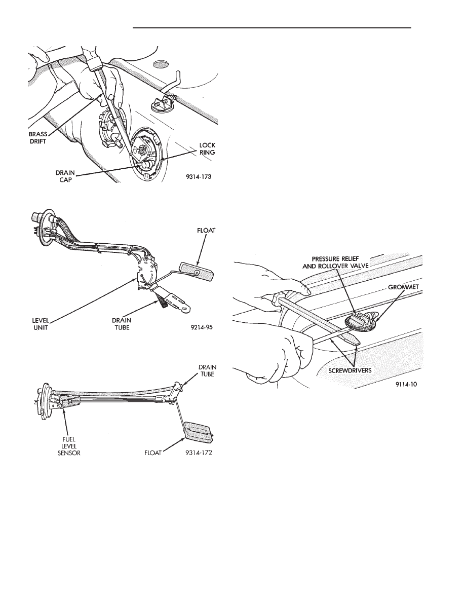
(1) Using a hammer and brass drift punch, care-
fully tap lock ring counterclockwise to release send-
ing unit (Fig. 9).
(2) Lift level unit and O-ring away from tank (Fig.
10 or Fig. 11).
INSTALLATION
WARNING: FUEL LEVEL SENSORS DESIGNED FOR
GASOLINE ONLY VEHICLES CANNOT BE USED ON
FLEXIBLE FUEL AA-BODY VEHICLES. WHEN SER-
VICING THE FUEL SYSTEM OF A FLEXIBLE FUEL
VEHICLE, ONLY USE ORIGINAL EQUIPMENT OR
EQUIVALENT REPLACEMENT COMPONENTS.
(1) Wipe seal area of tank clean and place a new
O-ring seal in position.
(2) Place sending unit in tank. Position lock ring
in place. Using a brass drift and hammer, tap ring in
a clockwise direction.
(3) Install tank.
Fig. 8 Level Sensor Diagnosis—Flexible Fuel
AA-Body
Fig. 7 Level Sensor Diagnosis—Except Flexible Fuel
AA-Body
Ä
FUEL SYSTEMS
14 - 19
FUEL TANK PRESSURE RELIEF AND ROLL-OVER
VALVE
REMOVAL
WARNING: RELEASE FUEL SYSTEM PRESSURE BE-
FORE SERVICING FUEL SYSTEM COMPONENTS.
WHEN
SERVICING
FLEXIBLE
FUEL
VEHICLES,
WEAR METHANOL RESISTANT GLOVES AND EYE
PROTECTION AND AVOID BREATHING FUMES. DO
NOT ALLOW METHANOL/GASOLINE MIXTURES TO
CONTACT SKIN. SERVICE VEHICLES IN WELL VEN-
TILATED AREAS AND AVOID IGNITION SOURCES.
NEVER SMOKE WHILE SERVICING THE VEHICLE.
(1) Remove fuel tank. Refer to Fuel Tank Removal in
this section.
(2) Wedge the blade of a screwdriver between the
rubber grommet and the fuel tank where the support
rib is located (Fig. 12). Do not wedge between the
valve and the grommet. This could damage the
valve during removal.
(3) Use a second screwdriver as a support to pry the
valve and grommet assembly from the tank.
(4) Place the valve upright on a flat surface. Push
down on the grommet and peel it off the valve.
Fig. 9 Level Sensor Removal—Typical
Fig. 10 Fuel Tank Level Sensor—Except Flexible
Fuel AA-Body
Fig. 11 Fuel Tank Level Sensor—Flexible Fuel
AA-Body
Fig. 12 Removing Pressure Relief/Rollover Valve
14 - 20
FUEL SYSTEMS
Ä
INSTALLATION
WARNING: FUEL PRESSURE RELIEF/ROLLOVER
VALVES DESIGNED FOR GASOLINE ONLY VEHI-
CLES CANNOT BE USED ON FLEXIBLE FUEL AA-
BODY VEHICLES. WHEN SERVICING THE FUEL
SYSTEM OF A FLEXIBLE FUEL VEHICLE, ONLY
USE ORIGINAL EQUIPMENT OR EQUIVALENT RE-
PLACEMENT COMPONENTS.
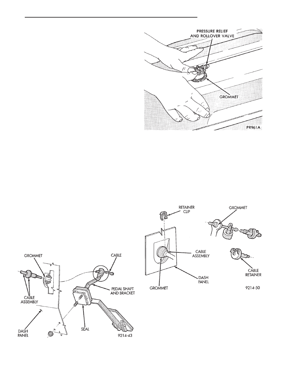
(1) Install the rubber grommet in the fuel tank by
working it around the curled lip of the tank (Fig. 13).
CAUTION: Only use power steering fluid to lubri-
cate the pressure relief/rollover valve grommet.
(2) Lightly lubricate the grommet with power
steering fluid only and push the valve downward into
the grommet. Twist valve until properly positioned.
(3) Install fuel tank (refer to fuel tank installa-
tion).
ACCELERATOR PEDAL AND THROTTLE CABLE
INDEX
page
page
Accelerator Pedal
. . . . . . . . . . . . . . . . . . . . . . . . 21
Throttle Cable
. . . . . . . . . . . . . . . . . . . . . . . . . . . 22
ACCELERATOR PEDAL
CAUTION: When servicing the accelerator pedal,
throttle cable or speed control cable, do not dam-
age or kink the control cable core wire.
REMOVAL
(1) Working from the engine compartment, hold
the throttle body throttle lever in the wide open po-
sition. Remove the throttle cable from the throttle
body cam.
(2) From inside the vehicle, hold up the pedal and
remove the cable retainer and throttle cable from the
upper end of the pedal shaft (Fig. 1 and Fig. 2).
(3) Working from the engine compartment, remove
nuts from accelerator pedal assembly studs (Fig. 1).
Remove assembly from vehicle.
INSTALLATION
(1) Position accelerator pedal assembly on dash
panel. Install retaining nuts. Tighten retaining nuts
to 12 N
Im (105 in. lbs.) torque.
Fig. 1 Accelerator Pedal and Throttle Cable—Front
View
Fig. 13 Installing Pressure Relief/Rollover Valve
Fig. 2 Accelerator Pedal and Throttle Cable—Rear
View
Ä
FUEL SYSTEMS
14 - 21
Нет комментариевНе стесняйтесь поделиться с нами вашим ценным мнением.
Текст