Chrysler Le Baron, Dodge Dynasty, Plymouth Acclaim. Manual — part 264

RADIATOR PRESSURE CAP
Radiators are equipped with a pressure cap which
releases pressure at some point within a range of
97-124 kPa (14-18 psi) (Fig. 7).
The system will operate at higher than atmospheric
pressure which raises the coolant boiling point allow-
ing increased radiator cooling capacity.
There is also a vent valve in the center of the cap that
allows a small coolant flow to the CRS tank. If valve is
stuck shut, the radiator hoses will be collapsed
on cool down. Clean the vent valve (Fig. 7) to
ensure proper sealing when boiling point is
reached.
There is also a gasket in the cap to seal to the top of
the filler neck so that vacuum can be maintained for
drawing coolant back into the radiator from the coolant
reserve system tank.
RADIATOR CAP TO FILLER NECK SEAL PRES-
SURE RELIEF CHECK
The pressure cap upper gasket (seal) pressure relief
can be checked by removing the overflow hose at the
radiator filler neck nipple (Fig. 7). Attach the Radiator
Pressure Tool to the filler neck nipple and pump air
into the radiator. Pressure cap upper gasket should
relieve at 69-124 kPa (10-18 psi) and hold pressure at
55 kPa (8 psi) minimum.
WARNING: THE WARNING WORDS DO NOT OPEN
HOT ON THE RADIATOR PRESSURE CAP IS A
SAFETY PRECAUTION. WHEN HOT, PRESSURE
BUILDS UP IN COOLING SYSTEM. TO PREVENT
SCALDING
OR
INJURY,
THE
RADIATOR
CAP
SHOULD NOT BE REMOVED WHILE THE SYSTEM IS
HOT AND/OR UNDER PRESSURE.
There is no need to remove the radiator cap at any
time except for the following purposes:
(1) Check and adjust antifreeze freeze point.
(2) Refill system with new antifreeze.
(3) Conducting service procedures.
(4) Checking for vacuum leaks.
WARNING: IF VEHICLE HAS BEEN RUN RECENTLY,
WAIT 15 MINUTES BEFORE REMOVING CAP. THEN
PLACE A SHOP TOWEL OVER THE CAP AND WITH-
OUT
PUSHING
DOWN
ROTATE
IT
COUNTER-
CLOCKWISE TO THE FIRST STOP. ALLOW FLUIDS
TO ESCAPE THROUGH THE OVERFLOW TUBE AND
WHEN THE SYSTEM STOPS PUSHING COOLANT
AND STEAM INTO THE CRS TANK AND PRESSURE
DROPS PUSH DOWN AND REMOVE THE CAP COM-
PLETELY. SQUEEZING THE RADIATOR INLET HOSE
WITH A SHOP TOWEL (TO CHECK PRESSURE) BE-
FORE AND AFTER TURNING TO THE FIRST STOP IS
RECOMMENDED.
PRESSURE TESTING RADIATOR CAPS
Dip the pressure cap in water, clean any deposits off
the vent valve or its seat and apply cap to end of
Radiator Pressure Tool. Working the plunger, bring the
pressure to 104 kPa (15 psi) on the gauge. If the
pressure cap fails to hold pressure of at least 97 kPa
(14 psi) replace cap. See CAUTION
If the pressure cap tests properly while positioned on
Radiator Pressure Tool, but will not hold pressure or
vacuum when positioned on the radiator. Inspect the
radiator filler neck and cap top gasket for irregularities
that may prevent the cap from sealing properly.
CAUTION: Radiator Pressure Tool is very sensitive to
small air leaks which will not cause cooling system
problems. A pressure cap that does not have a
history of coolant loss should not be replaced just
because it leaks slowly when tested with this tool.
Add water to the tool. Turn tool upside down and
recheck pressure cap to confirm that cap is bad.
INSPECTION
Hold the cap in hand, right side up (Fig. 7). The
vent valve at the bottom of the cap should open. If the
rubber gasket has swollen and prevents the valve from
opening, replace the cap.
Hold the cleaned cap in hand upside down. If any
light can be seen between vent valve and rubber
gasket, replace cap. Do not use a replacement cap
that has a spring to hold the vent shut.
Replacement cap must be of the type designed for
coolant reserve systems. This design assures coolant
return to radiator.
RADIATORS
The radiators are crossflow types (horizontal tubes)
with design features that provide greater strength as
well as sufficient heat transfer capabilities to keep the
engine satisfactorily cooled.
CAUTION: Plastic tanks, while stronger then brass
are subject to damage by impact, such as wrenches.
Fig. 7 Radiator Pressure Cap Filler Neck
7 - 18
COOLING SYSTEM
Ä
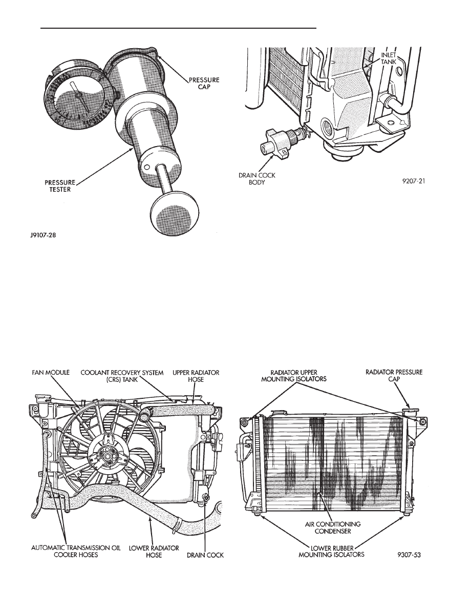
RADIATOR DRAINCOCK SERVICE
REMOVAL
(1) Turn the drain cock stem counterclockwise to
unscrew the stem. When the stem is unscrewed to
the end of the threads, pull the stem (Fig. 10) from
the radiator tank.
INSTALLATION
(1) Push the draincock assembly body into the
tank opening until it snaps into place.
(2) Tighten the draincock stem by turning clock-
wise to 2.0-2.7 N
Im (18-25 in. lbs.) torque.
RADIATOR COOLANT FLOW CHECK
To determine whether coolant is flowing through
the cooling system, use the following procedure:
(1) If engine is cold, idle engine until normal oper-
ating temperature is reached. Then feel the upper ra-
diator hose. If it is hot, coolant is circulating.
WARNING: DO NOT REMOVE RADIATOR PRES-
SURE CAP WITH THE SYSTEM HOT AND UNDER
PRESSURE
BECAUSE
SERIOUS
BURNS
FROM
COOLANT CAN OCCUR.
Fig. 9 Cooling Module—Typical
Fig. 8 Pressure Testing Radiator Cap
Fig. 10 Draincock Assembly—Typical
Ä
COOLING SYSTEM
7 - 19
(2) Remove radiator pressure cap when engine is
cold, Idle engine until thermostat opens, you should
observe coolant flow while looking down the filler
neck. Once flow is detected install radiator pressure
cap.
RADIATOR
REMOVAL
(1) Disconnect negative battery cable from battery.
WARNING:
DO
NOT
REMOVE
THE
CYLINDER
BLOCK PLUG OR THE RADIATOR DRAINCOCK
WITH THE SYSTEM HOT AND UNDER PRESSURE
BECAUSE SERIOUS BURNS FROM COOLANT CAN
OCCUR.
(2) Drain cooling system. Refer to Draining Cool-
ing System of this section.
(3) Remove hose clamps and hoses from the radia-
tor (Fig. 11). Remove coolant reserve system tank to
filler neck tube.
(4) Remove
automatic
transmission
hoses,
if
equipped.
(5) Remove fan and fan support assembly by dis-
connecting fan motor electrical connector. Remove
fan shroud retaining clips, located on the top and
bottom of the shroud for AA, AG, AJ and AP vehi-
cles. AC/AY vehicle retainer clips are located on the
top only. Lift shroud up and out of bottom shroud at-
tachment clips separating shroud from radiator. Fan
damage should always be avoided.
(6) Remove upper radiator mounting screws. Dis-
connect the engine block heater wire if equipped.
(7) Remove the air conditioning condenser attaching
screws located at the top front of the radiator,if
equipped.
Radiator can now be lifted free from engine compart-
ment. Care should be taken not to damage radia-
tor cooling fins or water tubes during removal.
INSTALLATION
(1) Slide radiator down into position behind radiator
support (yoke).
(2) Attach air conditioning condenser to radiator, if
equipped, with a force of approximately 10 lbs. to seat
the radiator assembly lower rubber isolators in the
mount holes provided.
(3) Tighten radiator mounting screws to 11.9N
Im
(105 in. lbs.).
(4) Connect
automatic
transmission
hoses,
if
equipped. Tighten hose clamps to 4 N
Im (35 in. lbs.).
(5) Slide fan shroud, fan and motor down into clips
on lower radiator flange. Replace shroud retaining
clips.
(6) Install upper and lower radiator hoses (including
coolant reserve hose).
(7) Connect fan motor electrical connection and con-
nect negative battery cable.
(8) Fill cooling system with coolant. Refer to Refill-
ing Cooling Systems. in this group.
(9) Operate engine until it reaches normal operating
temperature. Check cooling system and automatic
transmission for correct fluid levels.
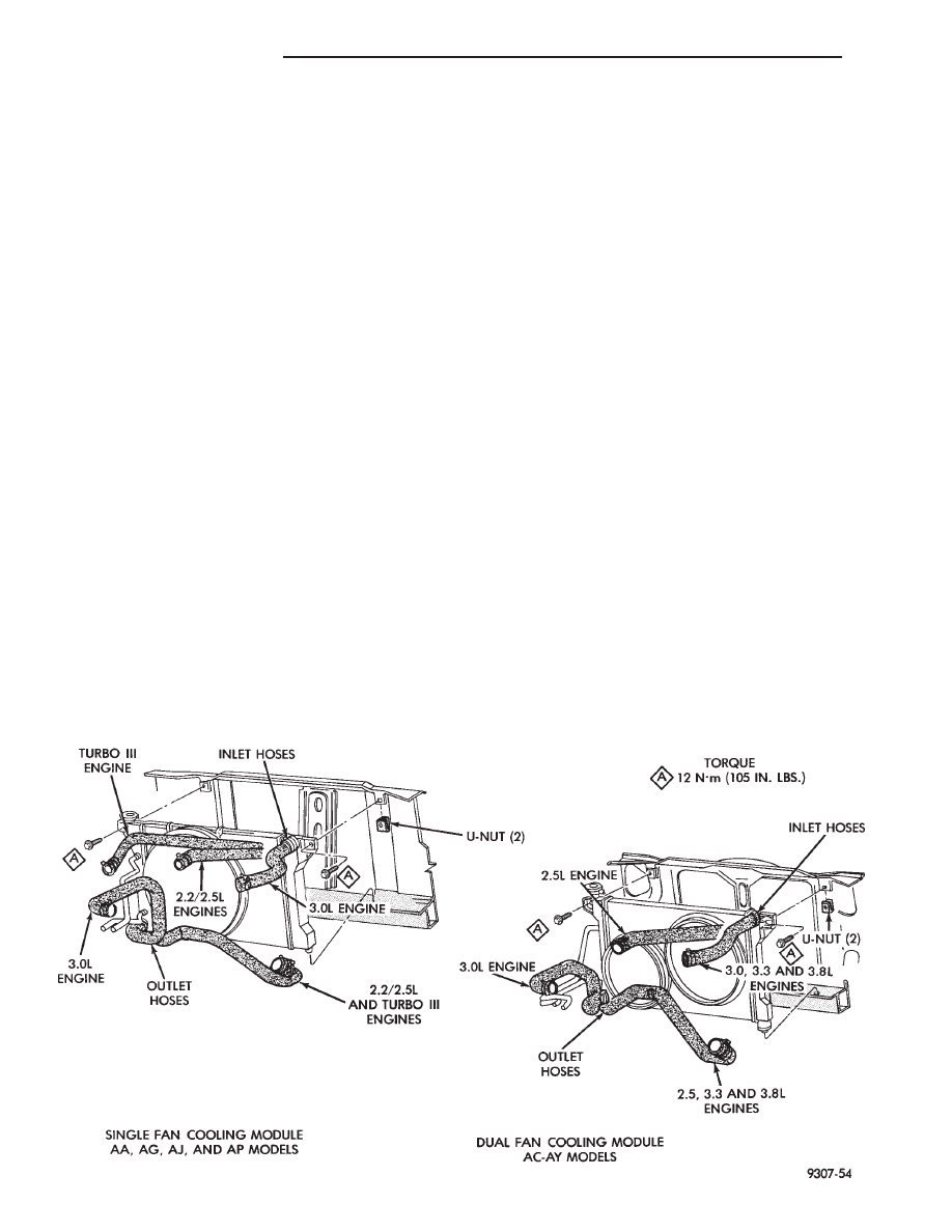
Fig. 11 Cooling Modules—All Models
7 - 20
COOLING SYSTEM
Ä

RADIATOR HOSES
The hoses are removed using Constant Tension
Clamp pliers to compress hose clamp.
A hardened, cracked, swollen or restricted hose
should be replaced. Do not damage radiator inlet and
outlet when loosening hoses.
Radiator hoses should be routed without any kinks
and indexed as designed. The use of molded hoses is
recommended.
Spring type hose clamps are used in all applica-
tions. If replacement is necessary replace with the
original style spring type clamp.
FANS
All models use electric motor driven cooling system
fans. The fan modules include a motor support which
may (depending on model) include a shroud. The
module is fastened to the radiator by screws with
U-nuts and retaining clips (Fig. 12).
All fan motors are one speed. Attempts to reduce
high temperature gauge reading by increasing en-
gine speed, at the same vehicle speed, can increase
high temperature.
SINGLE FAN
There are no repairs to be made to the fan. If the
fan is warped, cracked, or otherwise damaged, it
must be replaced with only the recommended part for
adequate strength, performance and safety (Fig. 13).
DUAL FAN MODULE—AC/AY BODY
The dual fan module (Fig. 11) is a combination of 2
fans mounted in a one piece shroud which are simul-
taneously activated. The dual fan system improves
engine cooling and air conditioning performance in hot
weather and severe driving conditions, while reducing
fan noise and power consumption.
REMOVAL
Disconnect electric motor lead. Remove fan module
to radiator fasteners and retaining clips. Remove as-
sembly from radiator support.
To remove fan from motor shaft, bench support the
motor and motor shaft, while removing the fan retain-
ing clip, so that the shaft and motor will not be
damaged by excessive force. Surface or burr re-
moval may be required to remove fan from motor
shaft. (Fig. 13). Do not permit the fan blades to touch
the bench.
INSTALLATION
Slide the fan on motor shaft. Support motor and
shaft as above while installing fan retaining clip.
Install assembly into pocket on lower radiator tank.
Attach retaining clips and fasteners to radiator tank.
Right side fastener is longer on A/C equipped
vehicles. Connect fan motor lead. For wiring dia-
grams of fan motor systems see Wiring Diagrams
Manual
RADIATOR FAN CONTROL—ALL EXCEPT V-6
ENGINE
Fan control is accomplished two ways. The fan al-
ways runs when the air conditioning compressor
clutch is engaged. In addition to this control, the fan is
turned on by the temperature of the coolant which is
sensed by the coolant temperature sensor which
Fig. 12 Servicing Fan Module
Fig. 13 Radiator Fan Retaining Clip—Typical
Ä
COOLING SYSTEM
7 - 21
Нет комментариевНе стесняйтесь поделиться с нами вашим ценным мнением.
Текст