Chrysler Le Baron, Dodge Dynasty, Plymouth Acclaim. Manual — part 591
(15) Install hood.
(16) Connect battery.
(17) Start engine and run until operating temper-
ature is reached.
(18) Adjust transmission or linkage if necessary.
ROCKER ARMS AND SHAFT ASSEMBLY
REMOVAL
(1) Remove upper intake manifold assembly. Refer
to Intake and Exhaust Manifolds, Group 11.
(2) Disconnect spark plug wires by pulling on the
boot straight out in line with plug.
(3) Disconnect closed ventilation system and evap-
oration control system from cylinder head cover.
(4) Remove cylinder head cover and gasket.
(5) Remove four rocker shaft bolts and retainers.
(6) Remove rocker arms and shaft assembly.
(7) If rocker arm assemblies are disassembled for
cleaning or replacement. Assemble rocker arms in
their original position.Refer to (Fig. 5) for rocker arm
for positioning on the shaft.
INSTALLATION
(1) Install rocker arm and shaft assemblies with
the stamped steel retainers in the four positions,
tighten to 28 N
Im (250 in. lbs.) (Fig. 5).
WARNING:
THE
ROCKER
ARM
SHAFT
SHOULD
BE
TORQUED
DOWN
SLOWLY,
STARTING WITH THE CENTERMOST BOLTS.
ALLOW 20 MINUTES TAPPET BLEED DOWN
TIME
AFTER
INSTALLATION
OF
THE
ROCKER SHAFTS BEFORE ENGINE OPERA-
TION.
(2) Clean cylinder head cover gasket surface. In-
spect cover for distortion and straighten if necessary.
(3) Clean head rail if necessary. Install a new gas-
ket and tighten cylinder head cover fasteners to 12
N
Im (105 in. lbs.).
(4) Install closed crankcase ventilation system and
evaporation control system.
(5) Install spark plug wires.
(6) Install upper intake manifold assembly. Refer to
Exhaust Systems and Intake Manifolds Group 11.
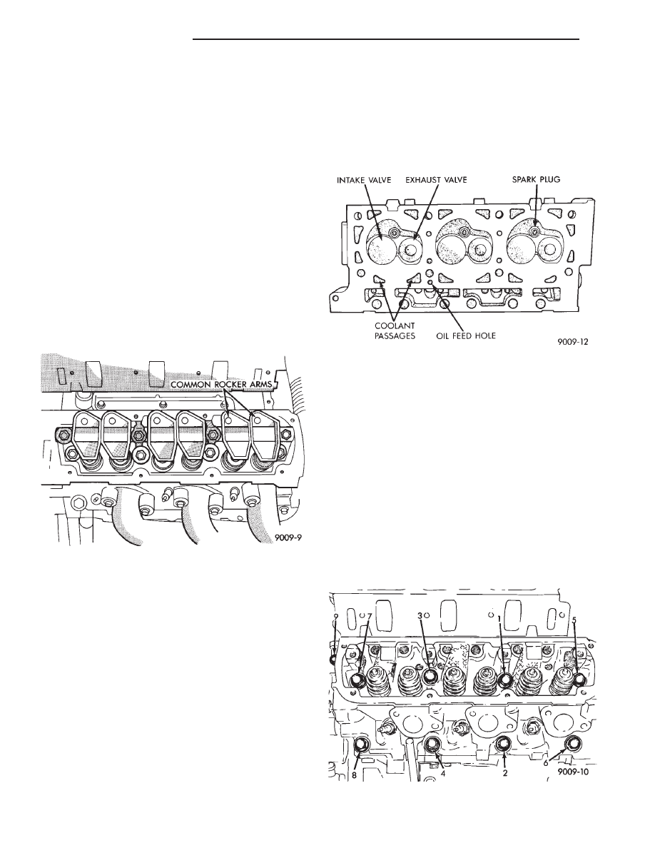
CYLINDER HEADS
The alloy aluminum cylinder heads shown in (Fig. 6)
are held in place by 9 bolts. The spark plugs are located
in peak of the wedge between the valves.
REMOVAL
(1) Drain cooling system refer to Cooling System
Group 7 for procedure and disconnect negative battery
cable.
Remove intake manifold, and throttle body. Refer to
Group 11 Exhaust System and Intake Manifold.
(2) Disconnect coil wires, sending unit wire, heater
hoses and by-pass hose.
(3) Remove closed ventilation system, evaporation
control system and cylinder head covers.
(4) Remove exhaust manifolds.
(5) Remove rocker arm and shaft assemblies. Re-
move push rods and identify to insure installation
in original locations.
(6) Remove the 9 head bolts from each cylinder head
and remove cylinder heads (Fig. 7).
Fig. 5 Rocker Arm Location Left Blank
Fig. 6 Cylinder Head Assembly
Fig. 7 Cylinder Head Bolts Location
9 - 102
3.3/3.8L ENGINE
Ä

INSPECTION
(1) Before cleaning, check for leaks, damage and
cracks.
(2) Clean cylinder head and oil passages.
(3) Check cylinder head for flatness (Fig. 8).
(4) Inspect all surfaces with a straightedge if there is
any reason to suspect leakage. If out of flatness exceeds
.019mm (.00075 inch). times the span length in inches
in any direction, either replace head or lightly machine
the head surface. As an example, if a 12 inch span is
1mm (.004 inch) out of flat, allowable is 12 x .019mm
(.00075 inch) equals .22mm (.009 in.) This amount of
out of flat is acceptable.
*Maximum of 0.2 mm (.008 inch) for grinding is
permitted.
CAUTION: This is a combined total dimension of
stock removal from cylinder head and block top
surface.
INSTALLATION
(1) Clean all surfaces of cylinder block and cylinder
heads.
(2) Install new gaskets on cylinder block (Fig. 9).
The Cylinder head bolts are torqued using the
torque yield method, they should be examined
BEFORE reuse. If the threads are necked down,
the bolts should be replaced (Fig. 10).
Necking can be checked by holding a scale or straight
edge against the threads. If all the threads do not
contact the scale the bolt should be replaced.
(3) Tighten the cylinder head bolts 1 thru 8 in the
sequence shown in (Fig. 11). Using the 4 step torque
turn method, tighten according to the following values:
• First-All to 61 NIm (45 ft. lbs.)
• Second-All to 88 NIm (65 ft. lbs.)
• Third-All (again) to 88 NIm (65 ft. lbs.)
• Fourth + 1/4 Turn Do not use a torque wrench
for this step
(4) Bolt torque after 1/4 turn should be over 122
N
Im(90 ft. lbs.). If not, replace the bolt.
(5) Tighten head bolt number 9 (Fig. 11) to 33 N
Im
(25 ft. lbs.) after head bolts 1 thru 8 have been tighten
to specifications.
(6) Inspect push rods and replace worn or bent rods.
(7) Install push rods, rocker arm and shaft assem-
blies with the stamped steel retainers in the four
positions, tighten to 28 N
Im (250 in. lbs.) (Fig. 12).
Fig. 8 Check Cylinder Head
Fig. 9 Head Gasket Installation
Fig. 10 Checking Bolts for Stretching (Necking)
Fig. 11 Cylinder Head Tightening Sequence
Ä
3.3/3.8L ENGINE
9 - 103

(8) Place new cylinder head cover gaskets in position
and install cylinder head covers. Tighten to 12 N
Im
(105 in. lbs.).
INTAKE MANIFOLD SEALING
The intake manifold gasket is a one-piece stamped
steel gasket with a sealer applied from the manufac-
turer. This gasket has end seals incorporated with it.
WARNING: INTAKE MANIFOLD GASKET IS
MADE OF VERY THIN METAL AND MAY CAUSE
PERSONAL INJURY, HANDLE WITH CARE.
(1) Clean all surfaces of cylinder block and cylinder
heads.
(2) Place a drop ( about 1/4 in. diameter) of Mopar
Silicone Rubber Adhesive Sealant or equivalent, onto
each of the four manifold to cylinder head gasket
corners (Fig. 13).
(3) Carefully install the intake manifold gasket (Fig.
14). Torque end seal retainer screws to 12 N
Im (105 in.
lbs.).
(4) Install intake manifold and (8) bolts and torque
to 1 N
Im (10 in. lbs.). Then tighten bolts to 22 NIm
(200 in. lbs.) in sequence shown in (Fig. 15). Then
tighten again to 22 N
Im (200 in. lbs.). After intake
manifold is in place, inspect to make sure seals
are in place. Refer to Group 11 Exhaust System and
Intake Manifold to complete Intake Manifold Assem-
bly.
(5) Install exhaust manifolds and tighten bolts to
27 N
Im (20 ft. lb.) and nuts to 20 NIm (15 ft. lbs.).
(6) Adjust spark plugs to specification in Electrical
Section, Group 8, and install the plugs.
VALVE SERVICE
VALVES AND VALVE SPRINGS
The valves are arranged in line in the cylinder
heads and inclined 18 degrees. The rocker shaft sup-
port are cast integral with the heads.
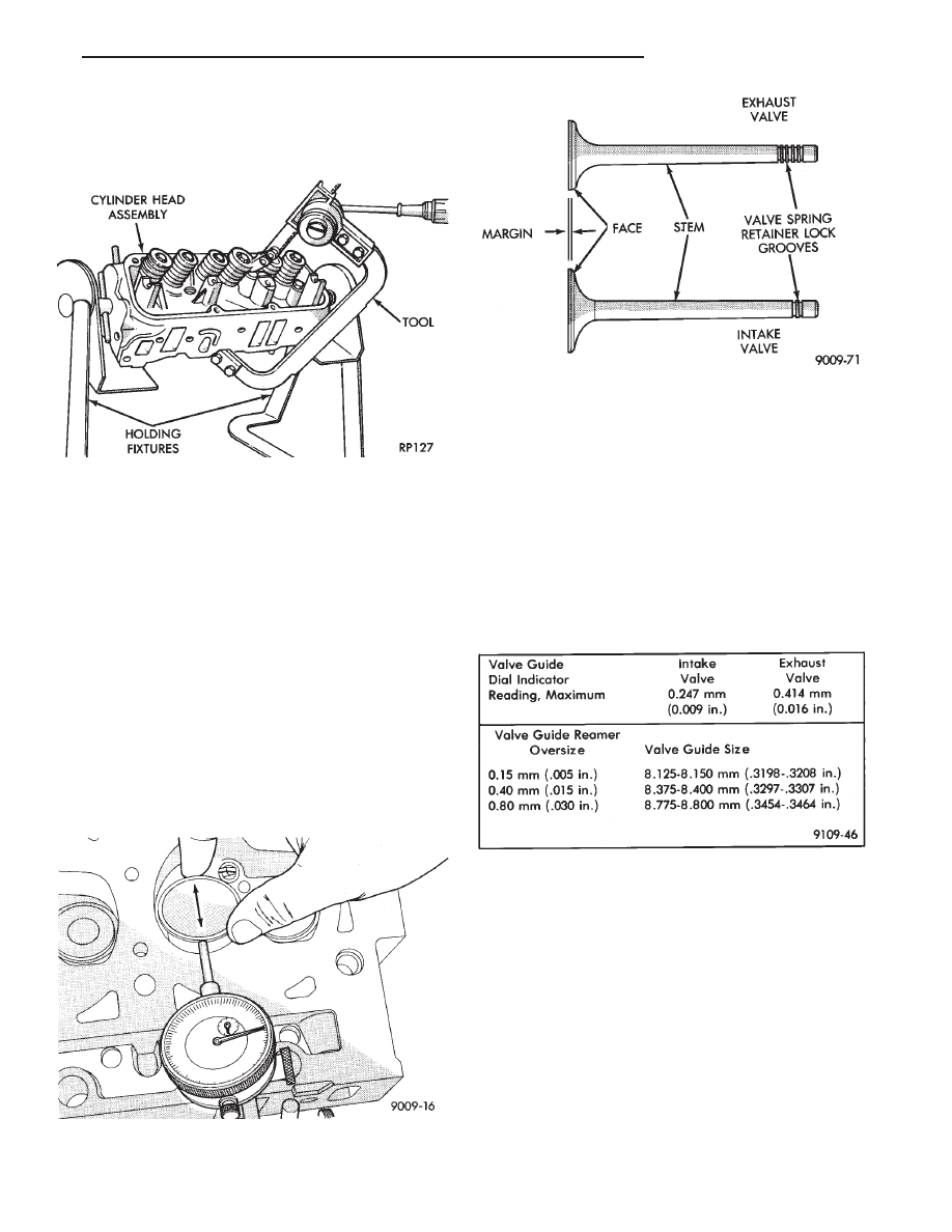
REMOVAL
(1) With cylinder head removed, compress valve
springs
using
Valve
Spring
Compressor
Tool
C-3422-B with adapter 6412 as shown in (Fig. 16).
(2) Remove valve retaining locks, valve spring re-
tainers, valve stem seals and valve springs.
Fig. 14 Intake Manifold Gasket Retainers
Fig. 15 Intake Manifold Removal and Installation
Fig. 12 Rocker Arm Shaft Retainers
Fig. 13 Intake Manifold Gasket Sealing
9 - 104
3.3/3.8L ENGINE
Ä
(3) Before removing valves,remove any burrs
from valve stem lock grooves to prevent damage
to the valve guides. Identify valves to insure instal-
lation in original location.
VALVE INSPECTION
(1) Clean valves thoroughly and discard burned,
warped and cracked valves.
(2) Measure valve stems for wear. Refer to specifica-
tions (Fig. 19).
Valve stems are chrome plated and should not
be polished.
(3) Remove carbon and varnish deposits from inside
of valve guides with a reliable guide cleaner.
(4) Measure valve stem guide clearance as follows:
(a) Install valve into cylinder head so it is 14mm
(.551 inch) off the valve seat. A small piece of hose
may be used to hold valve in place.
(b) Attach dial indicator Tool C-3339 to cylinder
head and set it at right angle of valve stem being
measured (Fig. 17).
(c) Move valve to and from the indicator. Refer to
specifications (Fig. 19).
Ream the guides for valves with oversized stems if
dial indicator reading is excessive or if the stems are
scuffed or scored.
(5) Service valves with oversize stems and over size
seals are available in 0.15mm (.005 inch), 0.40mm,
(.015 inch) and 0.80mm (.030 inch) oversize.
Oversize seals must be used with oversize
valves.
Reamers to accommodate the oversize valve stem are
as follows:
(6) Slowly turn reamer by hand and clean guide
thoroughly before installing new valve. Do not at-
tempt to ream the valve guides from standard
directly to 0.80mm (.030 inch) Use step procedure
of 0.15mm (.005 inch), 0.40mm (.015 inch) and
0.80mm (.030 inch) so the valve guides may be
reamed true in relation to the valve seat. After
reaming guides, the seat runout should be mea-
sured and resurfaced if necessary. See Refacing
Valves and Valve Seats.
VALVE GUIDES
Replace cylinder head if guide does not clean
up with 0.80mm (.030 inch) oversize reamer, or if
guide is loose in cylinder head.
Fig. 18 Intake and Exhaust Valves
Fig. 19 Valve Guide Specifications
Fig. 16 Compress Valve Springs with Special Tool
C-3422B with adapter 6412
Fig. 17 Measuring Valve Guide Wear
Ä
3.3/3.8L ENGINE
9 - 105
Нет комментариевНе стесняйтесь поделиться с нами вашим ценным мнением.
Текст