Chrysler Le Baron, Dodge Dynasty, Plymouth Acclaim. Manual — part 231
pared by the (CAB) and used to detect brake system
faults that would require Anti -Lock Braking to be
disabled.
The Boost Pressure Transducer is mounted on the
bottom of the hydraulic assembly, (Fig. 1) and moni-
tors booster servo pressure. The Primary Pressure
Transducer is mounted on the left side of the hydrau-
lic assembly and monitors primary master cylinder
pressure.
DIFFERENTIAL PRESSURE SWITCH
A non-latching Differential Pressure Switch is used
to detect a pressure difference greater than 2,068
kPa (300 psi.) between the primary and secondary
master cylinder hydraulic circuits. If detected, the
Differential Pressure Switch grounds the output of
the primary pressure transducer (circuit B-218). This
results in a 0.0 volt signal from the Primary Pres-
sure Transducer that is sensed by the (CAB) as a dif-
ferential pressure fault. The (CAB) will then light
the Red Brake Warning Lamp and the Amber Anti-
Lock Warning Lamp and disable the Anti-Lock brak-
ing function. See Fig. 1 for location of the differential
pressure switch.
PROPORTIONING VALVES
The
ABS
system
uses
screw-in
Proportioning
Valves in place of the conventional Height Sensing
Proportioning Valve. Each rear brake circuit has its
own screw-in Proportioning Valve that is attached to
the rear brake outlet ports of the hydraulic assembly
(Fig. 1). These valves limit brake pressure to the
rear brakes after a certain brake pressure is reached.
This improves front to rear wheel brake balance dur-
ing normal braking.
FILTERS-SERVICEABILITY
There is a screen filter in each of the two master
cylinder fill ports. There is also a low pressure filter
for the pump/motor. The filter is integral to the
Pump/Motor low pressure hose.
FLUID LEVEL SWITCH
A Low Fluid Switch is located in the hydraulic as-
sembly fluid reservoir, (Fig. 1). The switch consists of
a float and magnetic reed switch that closes when
low fluid is detected. The Low Fluid Switch is used
as an input, to the Red Brake Warning Lamp, the
(CAB), and the EVIC (if so equipped). When a low
fluid condition exists the switch will close, grounding
the low fluid circuit and illuminating the Red Brake
Warning Lamp. The (CAB) will disable the Anti-
Lock Function and light the Amber Anti-Lock Warn-
ing Lamp if vehicle is in motion above 3 mph. If
vehicle is not in motion, the Amber Anti-Lock Warn-
ing Lamp will NOT be lit.
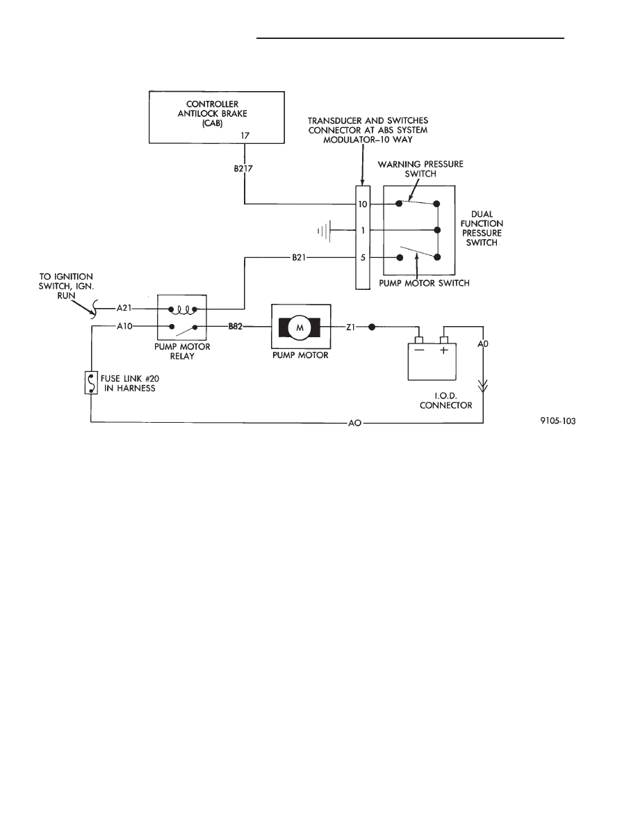
DUAL FUNCTION PRESSURE SWITCH WIRING DIAGRAM
5 - 78
ANTI-LOCK 10 BRAKE SYSTEM
Ä

PUMP/MOTOR ASSEMBLY
NOTE: The (CAB) does not control the opera-
tion of the pump/motor assembly.
The Pump/Motor Assembly is mounted to the tran-
saxle below the hydraulic assembly,(Fig. 3). Integral to
the Pump/Motor Assembly is an accumulator using a
sliding piston configuration with a nitrogen pre-charge
of 3,172 kPa (460 psi.) The Pump/Motor is an electri-
cally driven pump that takes low pressure brake fluid
from the hydraulic assembly fluid reservoir and pres-
surizes it. The pressurized fluid is then stored in the
piston accumulator and hydraulic bladder accumulator
for power assist and Anti-Lock Braking. Operation of
the Pump/Motor is controlled by the Dual Function
Pressure Switch through the Pump/Motor Relay. The
(CAB) does NOT control the Pump/Motor activa-
tion. Rubber isolators are used to mount the pump to
its bracket for noise isolation. The Pump/Motor Assem-
bly is connected to the Hydraulic Assembly with a low
pressure return hose and a high pressure hose. A filter
is located in the low pressure return line.
WHEEL SPEED SENSORS
One Wheel Speed Sensor (WSS), is located at each
wheel (Fig. 4, 5 and 6) and sends a small (AC) electrical
signal to the control module (CAB). This signal is
generated by magnetic induction. The magnetic induc-
tion is created when a toothed sensor ring (Tone Wheel)
passes by the stationary magnetic (Wheel Speed Sen-
sor). The (CAB) converts the (AC) electrical signal
generated at each wheel into a digital signal. If a wheel
locking tendency is detected, the (CAB) will then
modulate hydraulic pressure to prevent the wheel(s)
from locking.
The front Wheel Speed Sensor (Fig. 4) is mounted to
a boss on the steering knuckle, for both the Front
Wheel Drive and All Wheel Drive applications. The
Tone Wheel is part of the outboard constant velocity
joint housing.
The Rear Wheel Speed Sensor, is mounted to the
caliper mounting adapter (Fig. 5). The rear Tone
Wheel is an integral part of the rear disc brake rotor
hub (Fig. 6).
The speed sensor, to tone wheel air gap on all ap-
plications is NOT adjustable.
All 4 of the vehicles, Wheel Speed Sensors are ser-
viced individually as replaceable components.
The Front Wheel Drive front Tone Wheels are ser-
viced as an assembly with the front outboard con-
Fig. 3 Pump/Motor Assembly And Heat Shield
PRESSURE SWITCH AND PRESSURE TRANSDUCER WIRING
Ä
ANTI-LOCK 10 BRAKE SYSTEM
5 - 79
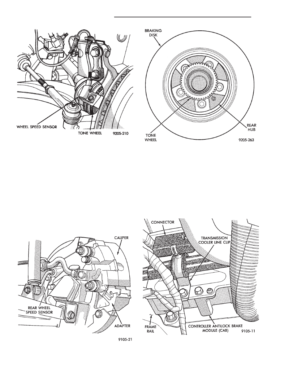
stant velocity joint housings. The rear Tone Wheels
are serviced as an assembly with the rear disc brake
rotor hub.
Correct Anti-Lock System operation is dependent
on wheel speed signals from the wheel speed sensors.
The vehicles’ wheels and tires must all be the same
size and type to generate accurate signals. In addi-
tion, the tires must be inflated to the recommended
pressures for optimum system operation. Variations
in wheel and tire size or significant variations in in-
flation pressure can produce inaccurate wheel speed
signals.
CONTROLLER ANTI-LOCK BRAKE (CAB)
The Anti-Lock Brake Controller is a small micro-
processor based device that monitors the brake sys-
tem and controls the system while it functions in
Anti-Lock Mode. The CAB is located under the bat-
tery tray and is mounted to the left frame rail (Fig.
7) and uses a 60-way system connector. The power
source for the CAB is through the ignition switch to
pin 60 of the controller. With the ignition in the
RUN or ON position. IF THE (ABS) CONTROL-
LER NEEDS TO BE REPLACED BE SURE THE
CORRECT CONTROLLER IS USED. THE CON-
TROLLER ANTI-LOCK BRAKE (CAB) IS NOT
ON THE CCD BUS
Fig. 5 Rear Wheel Speed Sensor
Fig. 4 Front Wheel Speed Sensor
Fig. 6 Rear Tone Wheel
Fig. 7 Location Controller Anti-Lock Brake (CAB)
5 - 80
ANTI-LOCK 10 BRAKE SYSTEM
Ä
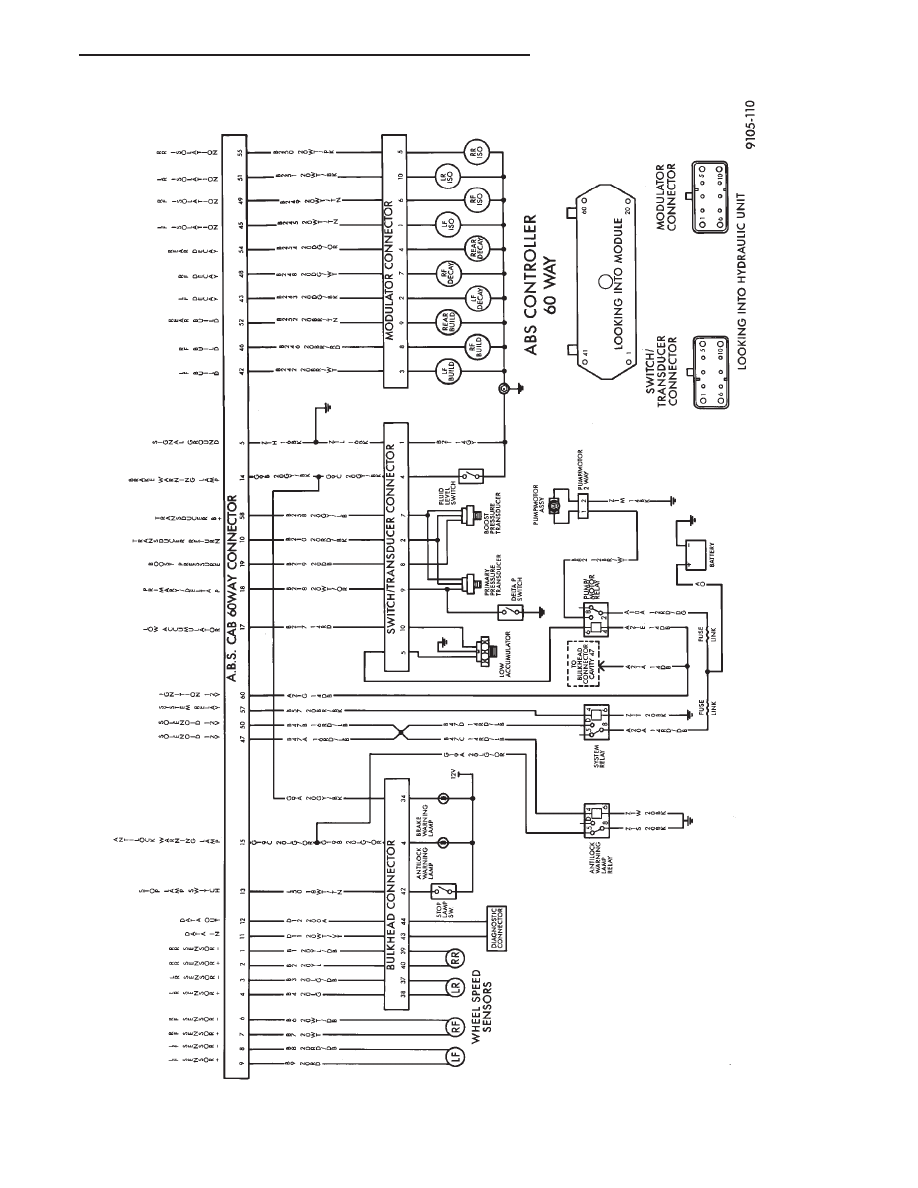
ABS
SYSTEM
WIRING
SCHEMATIC
Ä
ANTI-LOCK 10 BRAKE SYSTEM
5 - 81
Нет комментариевНе стесняйтесь поделиться с нами вашим ценным мнением.
Текст