Chrysler Le Baron, Dodge Dynasty, Plymouth Acclaim. Manual — part 358
POWER MIRRORS
CONTENTS
page
page
AUTOMATIC DAY/NIGHT INSIDE MIRROR
. . . . 7
AUTOMATIC DAY/NIGHT INSIDE MIRROR WITH
ULTRALIGHT HEADLAMP CONTROL
. . . . . . . 7
GENERAL INFORMATION . . . . . . . . . . . . . . . . . . 1
HEATED MIRROR
. . . . . . . . . . . . . . . . . . . . . . . . 2
INSIDE MIRROR/READING LAMPS BULB/LENS
REPLACEMENT
. . . . . . . . . . . . . . . . . . . . . . . . 6
INSIDE MIRROR/READING LAMPS
REPLACEMENT
. . . . . . . . . . . . . . . . . . . . . . . . 6
MIRROR ASSEMBLY REPLACEMENT—AA BODY
MIRROR ASSEMBLY REPLACEMENT—
AC AND AY BODIES
. . . . . . . . . . . . . . . . . . . . 5
MIRROR ASSEMBLY REPLACEMENT—AG BODY
. 5
MIRROR ASSEMBLY REPLACEMENT—AJ BODY
. 5
MIRROR ASSEMBLY REPLACEMENT—AP BODY
. 5
MIRROR MOTOR TEST PROCEDURE
. . . . . . . . 2
MIRROR SWITCH REPLACEMENT—AA BODY
. 3
MIRROR SWITCH REPLACEMENT—AC AND AY
BODIES
. . . . . . . . . . . . . . . . . . . . . . . . . . . . . . 4
MIRROR SWITCH REPLACEMENT—AG AND AJ
BODIES
. . . . . . . . . . . . . . . . . . . . . . . . . . . . . . 3
MIRROR SWITCH REPLACEMENT—AP BODY
. 4
MIRROR SWITCH TEST PROCEDURE
. . . . . . . 2
TEST PROCEDURES
. . . . . . . . . . . . . . . . . . . . . . 2
GENERAL INFORMATION
Electrically operated power mirrors are available
on all car lines. The mirrors are controlled by a sin-
gle switch assembly located either on the driver’s
door trim panel or on the center console.
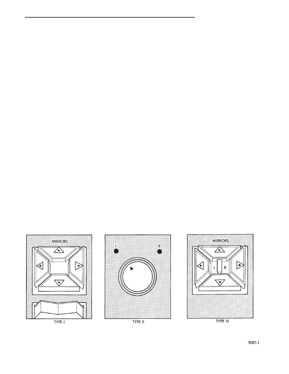
There are three types of switches currently used,
each uses a L (left) R (right) for mirror selection (Fig.
1). Type I, which uses a rocker for mirror selection
and four buttons for mirror movement direction.
Type II, uses a toggle switch which is rotated clock-
wise for the Right mirror or counterclockwise for the
Left mirror selection, and moved UP, DOWN, LEFT,
or RIGHT for mirror movement direction. Type III,
uses a paddle knob which is moved Left or Right for
mirror selection and four buttons for mirror move-
ment direction.
The motors which operate the mirrors are part of
the mirror assembly and cannot be replaced sepa-
rately.
All vehicles are equipped with an Ignition-Off
Draw Connector which is used when the vehicles are
originally shipped from the factory. This connector,
which is located near the battery, helps to prevent
battery discharge during storage. For specific connec-
tor type and location, refer Group 8W, Wiring Dia-
grams.
Fig. 1 Power Mirror Switches
Ä
POWER MIRRORS
8T - 1
This connector is included in the power mirror cir-
cuity except, for AC and AY body and should be
checked if the mirrors are inoperative.
MIRROR MOTOR TEST PROCEDURE
(1) Remove power mirror switch from mounting
position.
(2) Disconnect switch wiring harness at connector.
In the case of memory mirrors, (green 8-way mirror
connector and memory switch in drivers door panel),
the switch wiring disconnects from the cowl top har-
ness rather than the mirror harness.
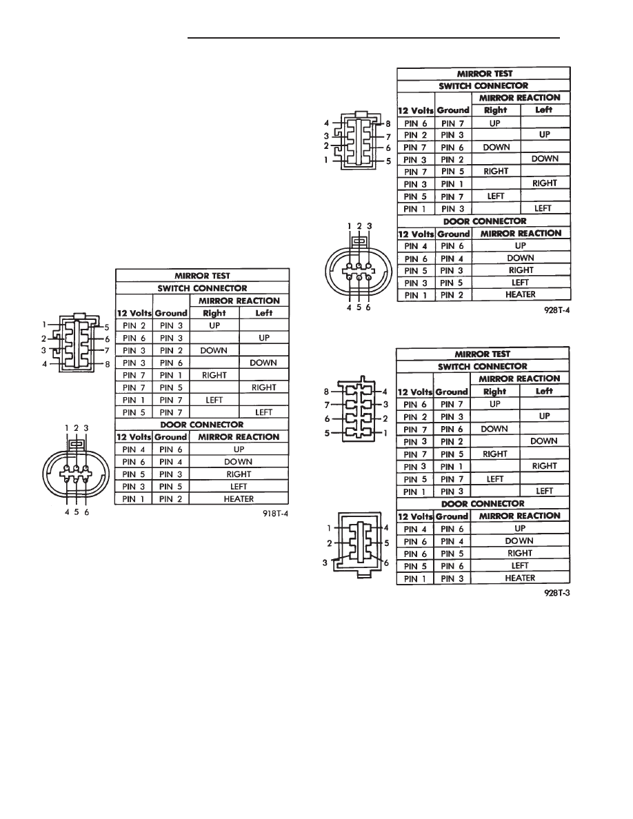
(3) Using two jumper wires, one connected to a 12
volt source, and the other connected to a good body
ground. Refer to the Mirror Test (Fig. 2 through 5)
for appropriate switch style, and for pin numbers.
(4) If results shown in the Fig. 2 through 5 are not
obtained, check for broken or shorted circuit, or re-
place mirror assembly as necessary.
MIRROR SWITCH TEST PROCEDURE
(1) Remove power mirror switch from mounting
position.
(2) Disconnect wiring harness at switch connector.
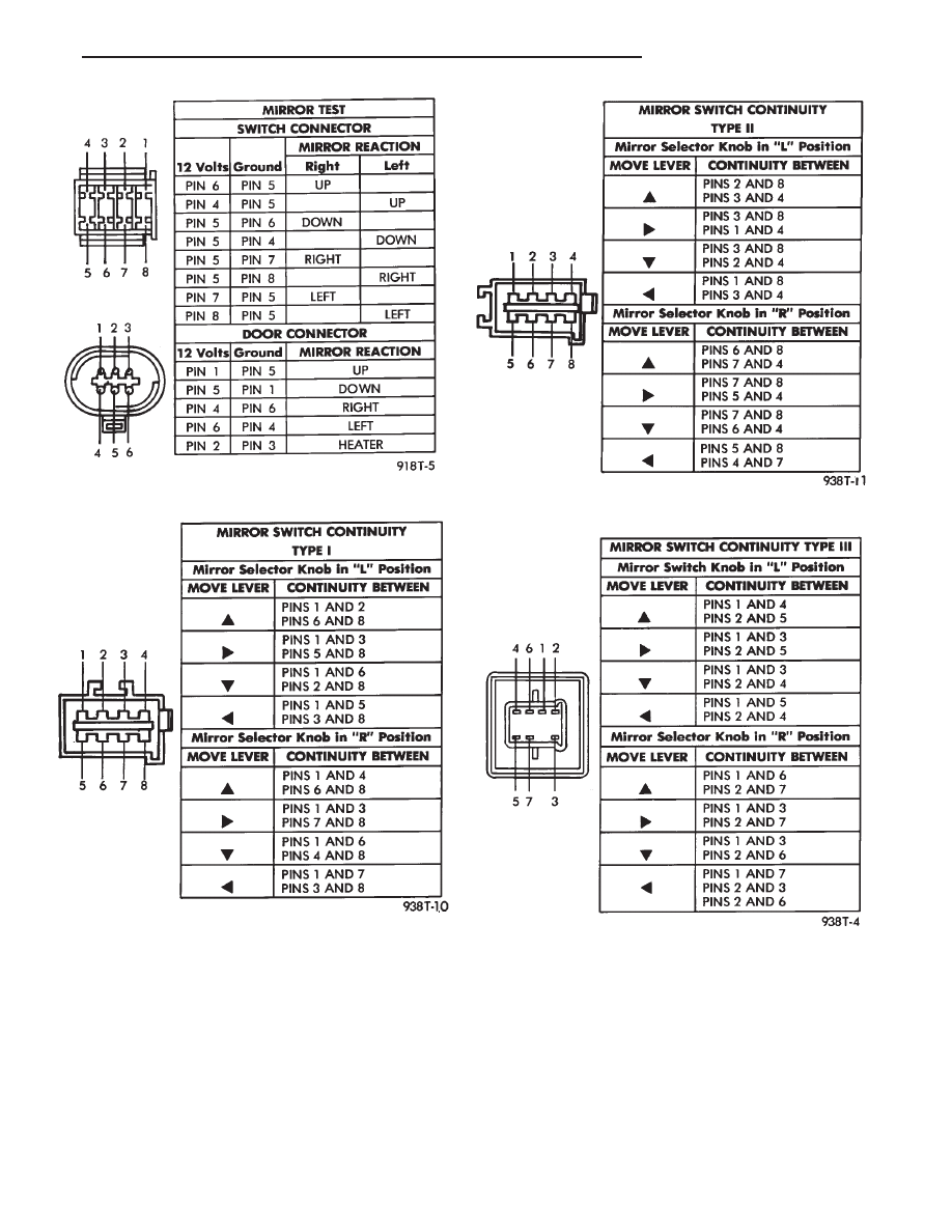
(3) Using a ohmmeter, test for continuity between
the terminals of the switch as shown in the Mirror
Switch Continuity for appropriate switch style (Fig. 6
through 8).
(4) If results shown in the Fig. 5, 6 and 7 are not
obtained, replace the switch.
HEATED MIRROR
Heated mirrors are available on all car lines except
AP Body, with Power Mirrors and Rear Window De-
fogger only. The heated mirror is controlled by the
rear window defogger switch. Only time that the
heated mirror is on is when the rear window defog-
ger is on.
TEST PROCEDURES
The mirror should be warm to the touch.
(a) If not check fuses.
(b) Test voltage at rear window defogger switch.
• If no voltage repair wire.
• Apply voltage to one wire and ground the other,
refer to Fig. 2 through 5 for pin numbers. Mirror
should become warm to the touch.
Fig. 2 MIRROR TEST—AP Body
Fig. 3 MIRROR TEST—AA Body
Fig. 4 MIRROR TEST—AC and AY Bodies
8T - 2
POWER MIRRORS
Ä
• If not remove mirror glass and test the wires for
continuity. If no continuity repair wires.
• If wires are OK, replace mirror glass.
• To test defogger switch refer to Group 8N, Rear
Window Defogger, Control Switch/Timer Relay Mod-
ule Test.
MIRROR SWITCH REPLACEMENT—AA BODY
(1) Remove door trim panel.
(2) Remove set screw from pillar trim bezel.
(3) Remove pillar trim bezel retaining screws.
(4) Disconnect switch wiring (Fig. 9).
(5) Remove switch from switch bezel.
(6) For installation, reverse above procedure.
MIRROR SWITCH REPLACEMENT—AG AND AJ
BODIES
(1) Carefully pry switch from switch bezel (Fig.
10).
(2) Remove switch wiring connector.
(3) For installation, reverse above procedure.
Fig. 5 MIRROR TEST—AG and AJ Bodies
Fig. 6 Type I Mirror Switch Test
Fig. 7 Type II Mirror Switch Test
Fig. 8 Type III Mirror Switch Test
Ä
POWER MIRRORS
8T - 3
Нет комментариевНе стесняйтесь поделиться с нами вашим ценным мнением.
Текст