Chrysler Le Baron, Dodge Dynasty, Plymouth Acclaim. Manual — part 253
MODULATOR ASSEMBLY (FIG. 1)
REMOVE
(1) Raise vehicle on jackstands or position vehicle
centered on a frame contact hoist. See Hoisting in the
Lubrication and Maintenance section of this manual.
(2) Disconnect and remove both battery cables from
battery.
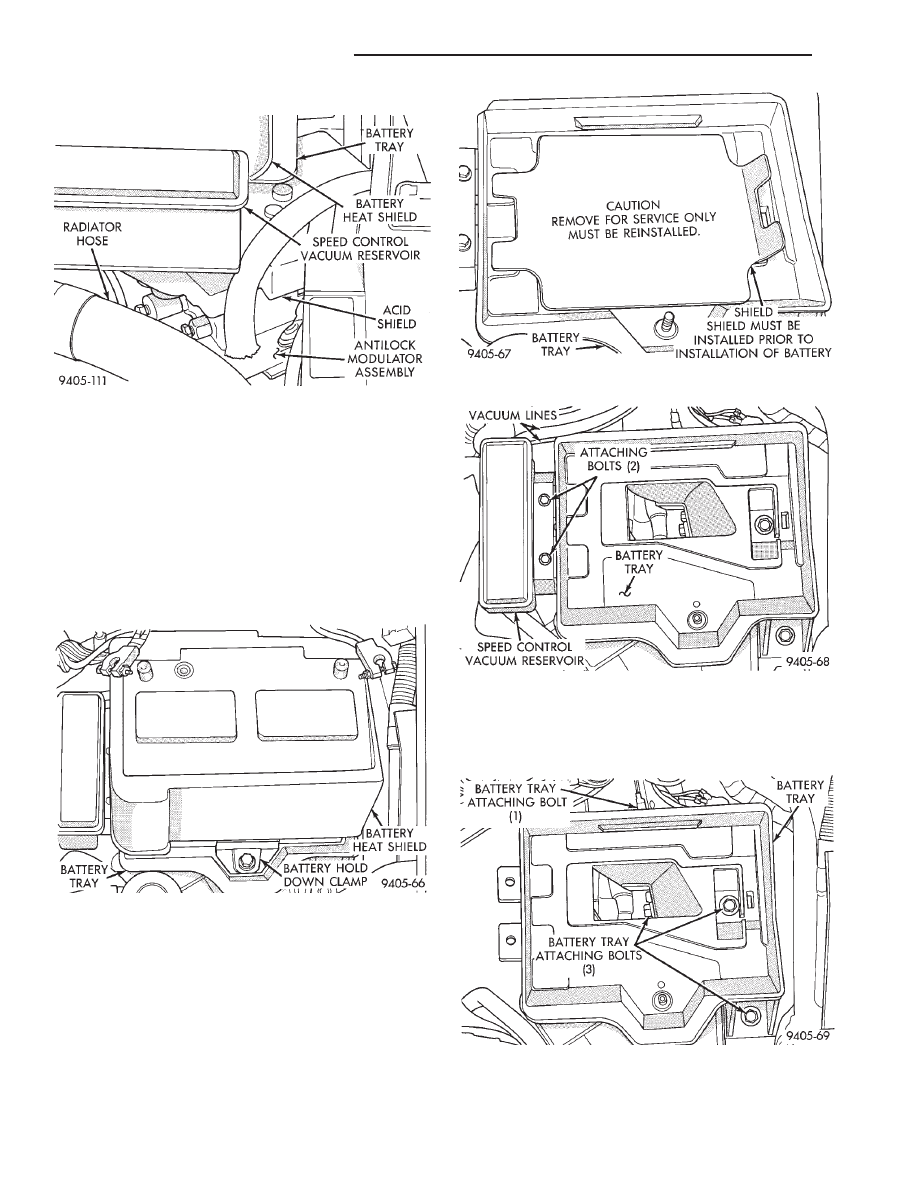
(3) Remove heat shield (Fig. 2) from battery. Then
remove battery hold down clamp (Fig. 2) and battery
from battery tray.
(4) Remove battery tray access cover (Fig. 3) from
battery tray. Do not discard, access cover MUST be
put back on battery tray, when battery is rein-
stalled.
(5) If equipped, remove the 2 bolts (Fig. 4) attaching
speed control vacuum reservoir to battery tray. Then
remove speed control system vacuum reservoir (Fig. 4)
from battery tray. Vacuum lines (Fig. 4) do not need
to be removed from vacuum reservoir.
(6) Remove the 4 bolts attaching battery tray (Fig.
5) to the frame rail and fender shield of vehicle.
Then remove battery tray from vehicle.
Fig. 3 Battery Tray Shield
Fig. 4 Speed Control System Vacuum Reservoir
Fig. 5 Battery Tray And Attaching Bolts
Fig. 1 Antilock Modulator Assembly Location In
Vehicle
Fig. 2 Battery Heat Shield And Hold Down Clamp
5 - 30
ANTILOCK 4 BRAKE SYSTEM
Ä
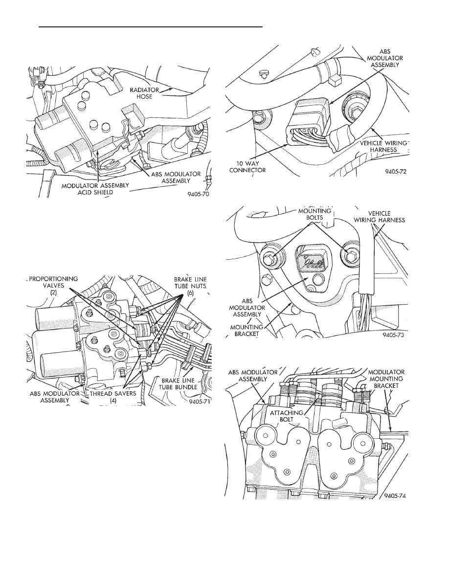
(7) Remove battery acid shield, (Fig. 6) from the ABS
modulator assembly.
(8) Remove the 6 tube nuts (Fig. 7), attaching hy-
draulic brake line tube bundle to modulator assembly,
thread savers and proportioning valves. Then remove
the hydraulic brake lines as an assembly, from the
modulator assembly. Brake lines do not need to be
loosened at junction block.
(9) Raise vehicle.
(10) Remove the vehicle’s wiring harness 10 way
connector, from the modulator assembly (Fig. 8).
(11) Remove 2 bolts (Fig. 9) attaching bottom of
modulator assembly to its mounting bracket.
(12) Lower vehicle.
(13) Remove bolt (Fig. 10) attaching front of modu-
lator assembly to mounting bracket.
(14) Remove modulator assembly from mounting
bracket and remove from vehicle.
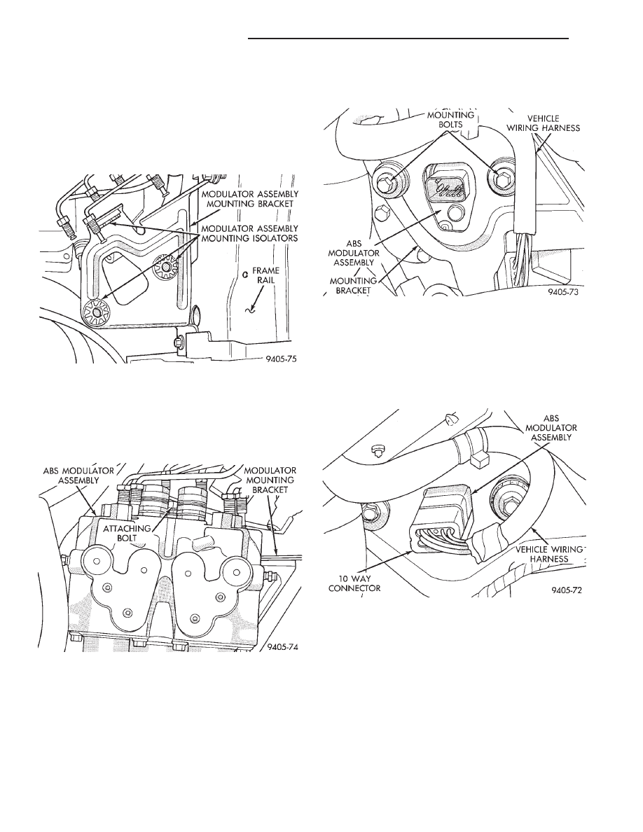
Fig. 8 Vehicle Wiring Harness Connection To
Modulator Assembly
Fig. 9 Modulator Assembly To Mounting Bracket
Attaching Bolts
Fig. 10 Front Modulator Assembly To Bracket Bolt
Fig. 6 ABS Modulator Assembly Acid Shield
Fig. 7 Hydraulic Brake Line Connections To Modula-
tor Assembly
Ä
ANTILOCK 4 BRAKE SYSTEM
5 - 31
INSTALL
NOTE: Before installing modulator assembly
back on mounting bracket, inspect the 3 modu-
lator assembly to bracket isolators (Fig. 11) for
any signs of deterioration or damage. Replace all
3 isolators if any show signs of damaged or
deterioration, before mounting modulator as-
sembly on bracket.
(1) Install
modulator
assembly
on
mounting
bracket.
(2) Install bolt (Fig. 12) attaching side of modulator
assembly to mounting bracket. Only loosely install
bolt at this time, do not tighten or torque.
(3) Raise vehicle.
CAUTION: Be sure mounting isolators are correctly
positioned on mounting bracket and modulator as-
sembly, before installing and torquing modulator
mounting bolts.
(4) Install the 2 modulator assembly to mounting
bracket attaching bolts (Fig. 13). Torque the 2 mount-
ing bolts to 28 N
Im (21 ft. lbs.).
(5) Install vehicle’s wiring harness 10 way connector
onto the modulator assembly (Fig. 14). Be sure lock
on vehicle wiring harness connector is fully en-
gaged with tab on modulator assembly electrical
connector.
(6) Lower vehicle.
(7) Torque front modulator assembly to mounting
bracket attaching bolt (Fig. 12) to 28 N
Im (21 ft. lbs.)
(8) Align the 6 disconnected hydraulic brake lines
with their appropriate fitting locations on modulator
assembly (Fig. 15). Then thread the 6 brake line tube
nuts by hand into the proportioning valves and thread
savers on modulator assembly.
(9) Using a crow foot and torque wrench (Fig. 16),
torque the 6 hydraulic brake line tube nuts to 18 N
Im
(159 in. lbs.).
Fig. 11 Modulator Assembly Mounting Isolators
Fig. 12 Front Modulator Assembly To Bracket Bolt
Fig. 13 Modulator Assembly To Bracket Attaching
Bolts.
Fig. 14 Electrical Connection To Modulator
Assembly
5 - 32
ANTILOCK 4 BRAKE SYSTEM
Ä
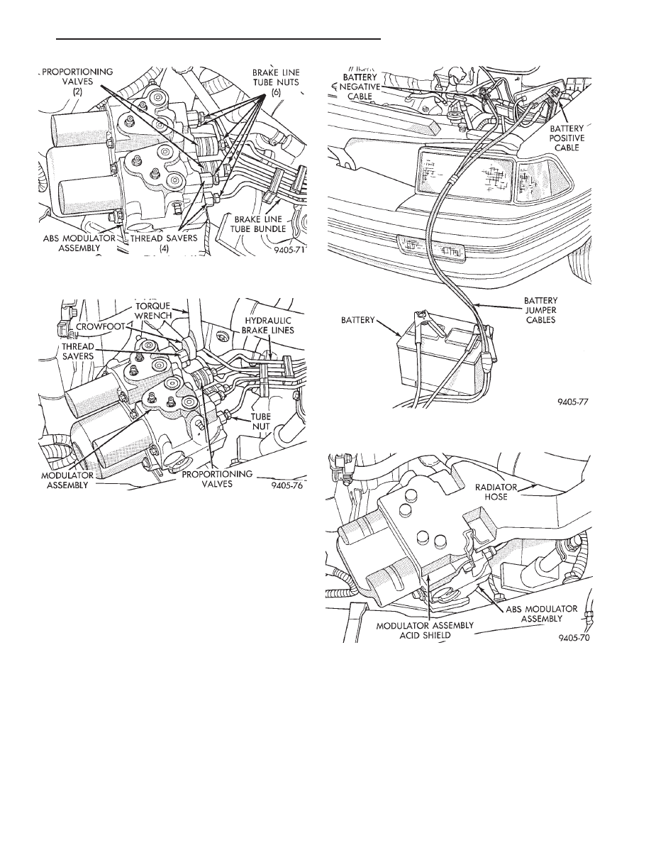
(10) Using approved battery jumper cables, attach
battery, to the vehicles negative and positive battery
cables (Fig. 17).
(11) Bleed the vehicles base brake and Antilock
brake hydraulic systems. Refer to Bleeding Bendix
Antilock 4 Brake System in this service manual
supplement for required bleeding procedure.
(12) Install the battery acid shield (Fig. 18) onto
modulator assembly. Be sure acid shield is securely
attached to modulator assembly before installing
battery tray.
(13) Install battery tray in vehicle. Then install the 4
bolts (Fig. 19) attaching battery tray to inner fender
and frame rail. Torque the 4 attaching bolts to 20 N
Im
(175 in.lbs.).
(14) If equipped, install speed control vacuum reser-
voir on battery tray. Then install the 2 speed control
vacuum reservoir attaching bolts (Fig. 20). Torque the
vacuum reservoir to attaching bolts to 4 N
Im (30 in.
lbs.).
(15) Install battery tray access cover (Fig. 21) on
battery tray. The access cover MUST be back on
battery tray, before battery is installed in battery
tray.
(16) Install battery on battery tray. Then install and
securely tighten battery hold down clamp (Fig. 22).
Then install battery heat shield, on battery (Fig. 22).
(17) Install battery cables on battery. Securely
tighten clamping bolts on battery cable terminals.
Fig. 15 Hydraulic Brake Line Connections at
Modulator Assembly
Fig. 16 Torquing Brake Line Connections To
Modulator Assembly
Fig. 17 Battery Connected To Vehicle For Bleeding
Modulator Assembly
Fig. 18 Modulator Assembly Acid Shield Installed
Ä
ANTILOCK 4 BRAKE SYSTEM
5 - 33
Нет комментариевНе стесняйтесь поделиться с нами вашим ценным мнением.
Текст