Chrysler Le Baron, Dodge Dynasty, Plymouth Acclaim. Manual — part 37

2.5L FLEXIBLE FUEL MULTI-PORT FUEL INJECTION—GENERAL DIAGNOSIS
INDEX
page
page
Fuel System Diagram
. . . . . . . . . . . . . . . . . . . . . 66
Visual Inspection
. . . . . . . . . . . . . . . . . . . . . . . . . 66
FUEL SYSTEM DIAGRAM
Refer to the Component Identification portion of
this section for a more complete description of the
components shown in Figure 1.
VISUAL INSPECTION
Perform a visual inspection for loose, disconnected,
or misrouted wires and hoses before diagnosing or
servicing the fuel injection system. A visual check
helps save unnecessary test and diagnostic time. A
thorough visual inspection includes the following
checks:
(1) Check Ignition Coil Electrical Connections (Fig.
2).
(2) Verify the electrical connector is attached to
the Canister Purge Solenoid (Fig. 3). Check the vac-
uum connections at the solenoid and canister.
(3) Verify the electrical connector is attached to
the MAP sensor (Fig. 4). Inspect the MAP sensor
vacuum hose for damage and leaks.
(4) Verify generator wiring and belt are correctly
installed and tightened.
Fig. 1 Flexible Fuel MPI Components
Fig. 2 Ignition Coil Electrical Connection
14 - 66
FUEL SYSTEMS
Ä

(5) Check Ignition Cable Routing and Attachment
(Fig. 5).
(6) Check both electrical connectors at the distrib-
utor.
(7) Check radiator fan electrical connector.
(8) Check the engine coolant temperature sensor
electrical connection. Inspect battery ground cable
connection (Fig. 6).
(9) Inspect the engine temperature sensor electri-
cal connection (Fig. 7).
(10) Check power brake booster and speed control
vacuum connections (Fig. 8).
(11) Check engine harness to main harness electri-
cal connections.
(12) Check park/neutral switch wiring connection
(Fig. 9).
(13) Ensure battery connections are clean and
tight.
(14) Inspect relay connections (Fig. 10)
(15) Ensure the 60-way connector is fully inserted
into the socket on the PCM (Fig. 11). Make sure the
wires are not stretched or pulled out of the connector.
Fig. 3 EVAP Purge Solenoid
Fig. 4 MAP Sensor
Fig. 5 Ignition Cable Mounting and Attachment
Fig. 6 Engine Coolant Temperature Sensor
Fig. 7 Engine Temperature Sensor Electrical
Connection
Ä
FUEL SYSTEMS
14 - 67

(16) Verify the harness connector is attached to
idle air control motor (Fig. 12).
(17) Verify the harness connector is attached to
the throttle position sensor (Fig. 12).
Fig. 8 Power Brake Booster and Speed Control
Vacuum Hose Connections
Fig. 9 Automatic Transaxle Electrical Connections
Fig. 10 Relay Identification
Fig. 11 PCM Electrical Connector
Fig. 12 TPS and Idle Air Control Motor
14 - 68
FUEL SYSTEMS
Ä
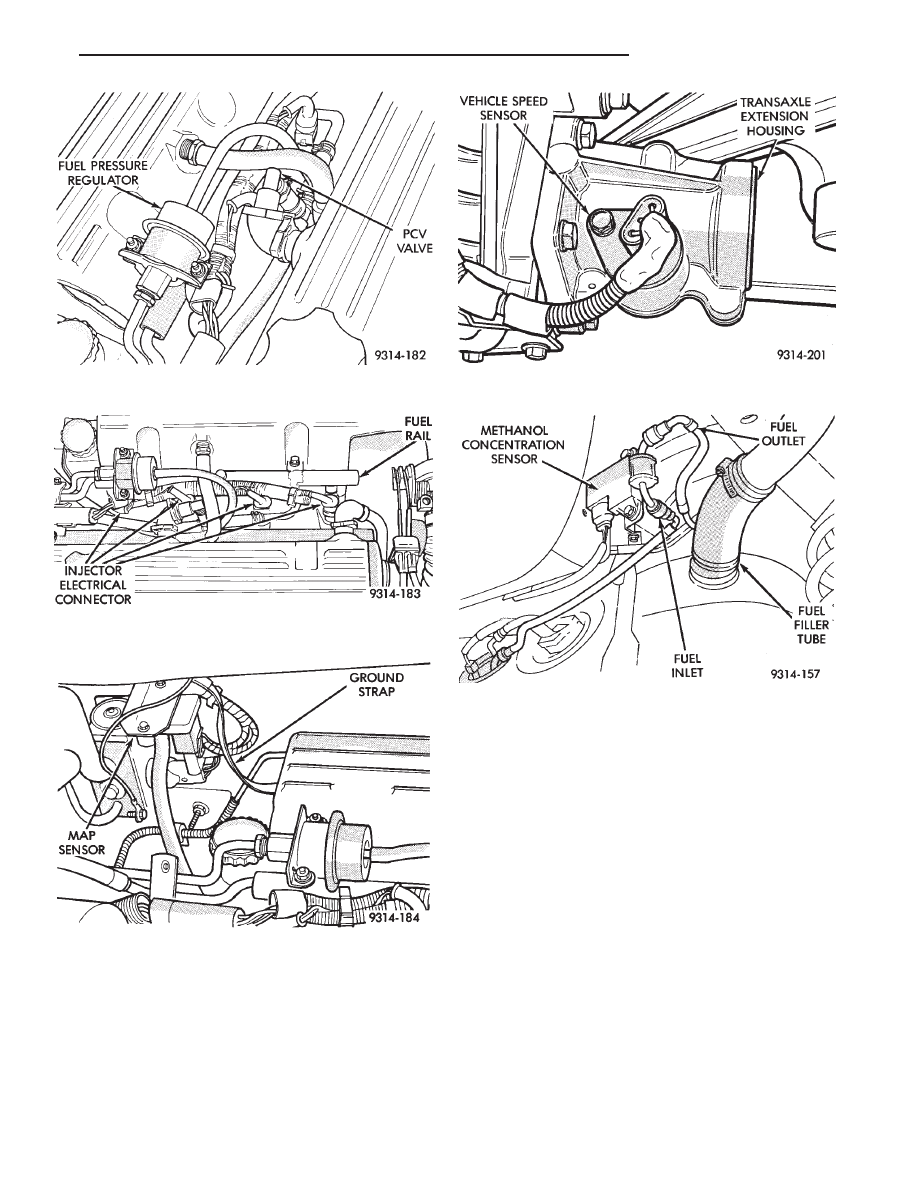
(18) Verify hose from PCV valve is securely at-
tached to the intake manifold vacuum port (Fig. 13).
(19) Check vacuum hose connection between vac-
uum source and fuel pressure regulator (Fig. 13).
(20) Inspect electrical connections at the fuel injec-
tors (Fig. 14).
(21) Inspect the heated oxygen sensor electrical
connector.
(22) Verify engine ground strap is attached to the
intake manifold and the dash panel (Fig. 15).
(23) Inspect all vacuum harness connections and
hoses for leaks.
(24) Verify the harness connector is attached to
the vehicle speed sensor (Fig. 16). Ensure the sensor
and connector are not damaged.
(25) Inspect hose and electrical connections at the
fuel pump. Ensure the electrical connector is fully
seated over the pump module terminals.
(26) Inspect electrical connections at the methanol
concentration sensor (Fig. 17).
Fig. 13 PCV Valve and Fuel Pressure Regulator
Fig. 14 Fuel Injector Electrical Connectors
Fig. 15 Ground Strap
Fig. 16 Vehicle Speed Sensor
Fig. 17 Methanol Concentration Sensor
Ä
FUEL SYSTEMS
14 - 69
Нет комментариевНе стесняйтесь поделиться с нами вашим ценным мнением.
Текст