Chrysler Le Baron, Dodge Dynasty, Plymouth Acclaim. Manual — part 346
CLOCKSPRING
WARNING: BEFORE BEGINNING ANY AIR BAG
SYSTEM REMOVAL OR INSTALLATION PROCE-
DURES, REMOVE AND ISOLATE THE BATTERY
NEGATIVE (-) CABLE (GROUND) FROM THE VEHI-
CLE BATTERY. THIS IS THE ONLY SURE WAY TO
DISABLE THE AIR BAG SYSTEM. FAILURE TO DO
SO COULD RESULT IN ACCIDENTAL AIR BAG DE-
PLOYMENT, AND POSSIBLE INJURY.
WHEN AN UNDEPLOYED AIR BAG ASSEMBLY
IS TO BE REMOVED FROM THE STEERING
WHEEL, DISCONNECT BATTERY GROUND CA-
BLE AND ISOLATE. ALLOW SYSTEM CAPACI-
TOR TO DISCHARGE FOR TWO MINUTES, THEN
BEGIN AIR BAG REMOVAL.
REMOVAL
(1) Place the front wheels in the straight ahead po-
sition before starting the repair.
(2) Disconnect battery negative cable and isolate.
(3) Wait two minutes for the reserve capacitor to
discharge before removing undeployed module.
(4) Remove the air bag module.
(5) Remove Speed Control switch and connector if
so equipped or cover.
(6) Disconnect horn terminals.
(7) Remove the steering wheel.
(8) Remove
upper
and
lower
steering
column
shrouds to gain access to clockspring wiring.
(9) Disconnect the 2-way connector between the
clockspring and the instrument panel wiring harness
on top of the fuse block.
(10) To remove, pull clockspring assembly from the
steering column by lifting locating fingers as neces-
sary. The clockspring cannot be repaired, and must
be replaced if faulty.
INSTALLATION
(1) Snap clockspring onto the steering column. If
the clockspring is not properly positioned, follow the
clockspring centering procedure before installing
steering wheel.
(2) Connect the clockspring to the instrument
panel harness, ensure wiring locator clips are prop-
erly seated on wiring trough. Ensure harness locking
tabs are properly engaged.
(3) Install steering column shrouds. Be sure air
bag wire is inside of shrouds.
(4) Front wheels should still be in the straight-
ahead position. Install steering wheel, ensure the
flats on hub align with clockspring. Pull the horn
lead through the smaller upper hole. Pull the air bag
and speed control leads through the larger bottom
hole. Ensure leads are not pinched under the steer-
ing wheel.
(5) Connect the horn lead wire, then the air bag
lead wire to the air bag module.
(6) Install the air bag module and tighten nuts to
9 to 11 N
Im (80 to 100 in. lb.) torque.
(7) Install speed control switch and connector or
cover.
(8) Do not connect battery negative cable. Refer to
Air Bag Systems Check for proper procedure.
CLOCKSPRING CENTERING PROCEDURE
If the rotating tape within the clockspring is not
positioned properly with the steering wheel and the
front wheels, the clockspring may fail during use.
The following procedure MUST BE USED to center
the clockspring if it is not known to be properly po-
sitioned, or if the front wheels were moved from the
straight ahead position.
WARNING: BEFORE BEGINNING ANY AIR BAG
SYSTEM REMOVAL OR INSTALLATION PROCE-
DURES, REMOVE AND ISOLATE THE BATTERY
NEGATIVE (-) CABLE (GROUND) FROM THE VEHI-
CLE BATTERY. THIS IS THE ONLY SURE WAY TO
DISABLE THE AIR BAG SYSTEM. FAILURE TO DO
THIS COULD RESULT IN ACCIDENTAL AIR BAG
DEPLOYMENT AND POSSIBLE INJURY.
WHEN AN UNDEPLOYED AIR BAG ASSEMBLY
IS TO BE REMOVED FROM THE STEERING
WHEEL, DISCONNECT BATTERY GROUND CA-
BLE AND ISOLATE. ALLOW SYSTEM CAPACI-
TOR TO DISCHARGE FOR TWO MINUTES, THEN
BEGIN AIR BAG REMOVAL.
(1) Place front wheels in the straight ahead posi-
tion.
(2) Wait two minutes for the reserve capacitor to
discharge before removing undeployed module.
(3) Refer to Steering Wheel procedures for removal
of air bag module and steering wheel.
(4) Depress the two plastic locking pins to disen-
gage locking mechanism (Fig. 10).
(5) Keeping locking mechanism disengaged, rotate
the clockspring rotor in the CLOCKWISE DIREC-
TION to the end of travel. Do not apply excessive
torque.
(6) From the end of travel, rotate the rotor two full
turns and a half in the counterclockwise direction.
The horn wire should end up at the top and the squib
wire at the bottom. Engage clockspring locking
mechanism.
(7) Refer to Steering Wheel procedures for installa-
tion of steering wheel and air bag module.
(8) Do not connect battery negative cable. Refer to
Air Bag System Check for proper procedure.
8M - 6
RESTRAINT SYSTEMS
Ä

STEERING WHEEL
WARNING: BEFORE BEGINNING ANY AIR BAG
SYSTEM REMOVAL OR INSTALLATION PROCE-
DURES, REMOVE AND ISOLATE THE BATTERY
NEGATIVE (-) CABLE (GROUND) FROM THE VEHI-
CLE BATTERY. THIS IS THE ONLY SURE WAY TO
DISABLE THE AIR BAG SYSTEM. FAILURE TO DO
THIS COULD RESULT IN ACCIDENTAL AIR BAG
DEPLOYMENT AND POSSIBLE PERSONAL INJURY.
WHEN AN UNDEPLOYED AIR BAG ASSEMBLY
IS TO BE REMOVED FROM THE STEERING
WHEEL, DISCONNECT BATTERY GROUND CA-
BLE AND ISOLATE. ALLOW SYSTEM CAPACI-
TOR
TO
DISCHARGE
FOR
TWO
MINUTES.
BEGIN AIR BAG REMOVAL.
REMOVAL
(1) Make sure front wheels are straight, and steer-
ing column is locked in place.
(2) Disconnect battery negative cable and isolate.
(3) Wait two minutes for the reserve capacitor to
discharge before removing undeployed module.
(4) Remove four nuts attaching air bag module
from the back side of steering wheel.
(5) Lift module, and disconnect connector from rear
of module.
(6) Remove speed control switch and connector if
so equipped or cover.
(7) Remove steering wheel retaining nut.
(8) Remove steering wheel with steering wheel
puller Tool C-3428B.
INSTALLATION
(1) If the clockspring is not properly positioned or
if front wheels were moved, follow the clockspring
centering procedure before installing steering wheel.
With the front wheels in the straight ahead position.
Position the steering wheel on the steering column.
Making sure to fit the flats on the hub of the steer-
ing wheel with the formations on the inside of the
clockspring. Pull the air bag and speed control wires
through the lower, larger hole in the steering wheel
and the horn wire through smaller hole at the top.
Make sure not to pinch wires (Fig. 11).
(2) Install retaining nut, and tighten to 61 N
Im (45
ft. lbs.) torque.
(3) Connect horn wiring lead.
(4) Connect
4-way
connector
to
speed
control
switch and attach switch to steering wheel.
(5) Connect air bag lead wire to air bag module,
and secure module to steering wheel.
(6) Do not connect negative battery cable. Refer to
Air Bag System Check for proper procedure.
STEERING COLUMN SWITCHES
This procedure covers the removal and installation
of the steering wheel and clockspring. Once the
steering wheel and clockspring have been removed,
refer to the appropriate section of this service man-
ual for switch replacement.
WARNING: BEFORE BEGINNING ANY AIR BAG
SYSTEM REMOVAL OR INSTALLATION PROCE-
DURES, REMOVE AND ISOLATE THE BATTERY
NEGATIVE (-) CABLE (GROUND) FROM THE VEHI-
CLE BATTERY. THIS IS THE ONLY SURE WAY TO
DISABLE THE AIR BAG SYSTEM. FAILURE TO DO
THIS COULD RESULT IN ACCIDENTAL AIR BAG
DEPLOYMENT AND POSSIBLE INJURY.
WHEN AN UNDEPLOYED AIR BAG ASSEMBLY
IS TO BE REMOVED FROM THE STEERING
WHEEL, DISCONNECT BATTERY GROUND CA-
BLE AND ISOLATE. ALLOW SYSTEM CAPACI-
Fig. 10 Clockspring (Auto-Locking)
Fig. 11 Steering Wheel Wiring
Ä
RESTRAINT SYSTEMS
8M - 7
TOR
TO
DISCHARGE
FOR
TWO
MINUTES.
BEGIN AIR BAG REMOVAL.
REMOVAL
(1) Disconnect battery negative cable, and isolate.
(2) Wait two minutes for the reserve capacitor to
discharge before removing undeployed module.
(3) Remove four nuts attaching air bag module
from the back side of steering wheel.
(4) Lift module, and disconnect connector from rear
of module.
(5) Remove speed control switch and connector if
so equipped or cover.
(6) Remove steering wheel.
(7) Unsnap clockspring, and remove it.
(8) Refer to the appropriate section for switch re-
placement.
INSTALLATION
(1) Snap clockspring on to steering column. Assure
the 4 way connector is still seated.
(2) Install steering wheel.
(3) Install speed control switch and connector or
cover.
(4) Connect clockspring wiring connector to the
module.
(5) Install four nuts to module, and tighten to 9 to
11 N
Im (80 to 100 in. lbs.) torque.
(6) Do not connect negative battery cable. Refer to
Air Bag System Check for proper procedure.
8M - 8
RESTRAINT SYSTEMS
Ä
REAR WINDOW DEFOGGER
CONTENTS
page
page
CONTROL SWITCH/TIMER RELAY MODULE
. . 1
GENERAL INFORMATION . . . . . . . . . . . . . . . . . . 1
REPAIR GRID LINES, TERMINALS AND PIGTAILS . 3
SERVICE PROCEDURES
. . . . . . . . . . . . . . . . . . . 1
GENERAL INFORMATION
For proper operation of the Rear Window Defogger
system refer to the Owner’s Manual.
Vehicles equipped with an electrically heated rear
window defogger also have a 40/90 amp generator.
The system consists of a rear glass with two verti-
cal bus bars and a series of electrically connected
grid lines fired on the inside surface. A control
switch and a timer relay combined into a single as-
sembly is used on all models (Fig.1).
Circuit protection is provided by a fusible link, lo-
cated in the charging circuit, for the heated grid cir-
cuit and by a fuse for the relay control circuit.
When the switch is turned to the ON position, cur-
rent is directed to the rear defogger grid lines. The
heated grid lines heat the rear glass to clear the sur-
face of fog or frost.
CAUTION: Grid lines can be damaged or scraped
off with sharp instruments, care should be taken in
cleaning glass or removing foreign materials, de-
cals or stickers. Normal glass cleaning solvents or
hot water used with rags or toweling is recom-
mended.
CONTROL SWITCH/TIMER RELAY MODULE
The control switch and timer relay are integrated
into a single panel or console mounted assembly. Ac-
tuating the switch energizes the circuit which allows
current to flow through the grid lines. Upon initial
actuation for approximately ten minutes, or until ei-
ther the switch or ignition is turned off. An indicat-
ing lamp illuminates a lens inlaid in the control
switch.
SERVICE PROCEDURES
Electrically heated rear window defogger operation
can be checked in vehicle in the following manner:
(1) Turn ignition ON.
(2) Turn rear window defogger control switch ON.
(3) Using a ammeter on the battery. Turn the De-
fogger control switch ON, a distinct increase in am-
perage draw should be noted.
(4) The rear window defogger operation can be
checked by feeling the glass. A distinct difference in
temperature between the grid lines and adjacent
clear glass can be detected in three to four minutes
of operation.
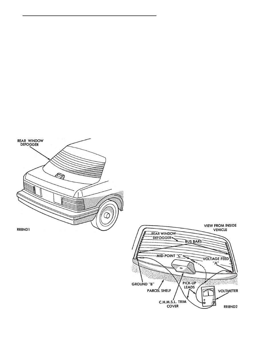
(5) Using a DC voltmeter (Fig. 2) contact terminal
B with the negative lead, and terminal A with the
positive lead. The voltmeter should read 10-14 volts.
Fig. 1 Rear Window Defogger—Typical
Fig. 2 Rear Glass Grid Line Test—Typical
Ä
REAR WINDOW DEFOGGER
8N - 1
Нет комментариевНе стесняйтесь поделиться с нами вашим ценным мнением.
Текст